
Display panel and display device

A technology of display panel and display area, applied in static indicators, instruments, diodes, etc., can solve the problems of differences in light-emitting elements and uneven display brightness, and achieve the effects of reducing attenuation, improving light transmittance, and reducing resistive load.

Active Publication Date: 2021-01-05
WUHAN TIANMA MICRO ELECTRONICS CO LTD
View PDF7 Cites 7 Cited by
  • Summary
  • Abstract
  • Description
  • Claims
  • Application Information

AI Technical Summary

Problems solved by technology

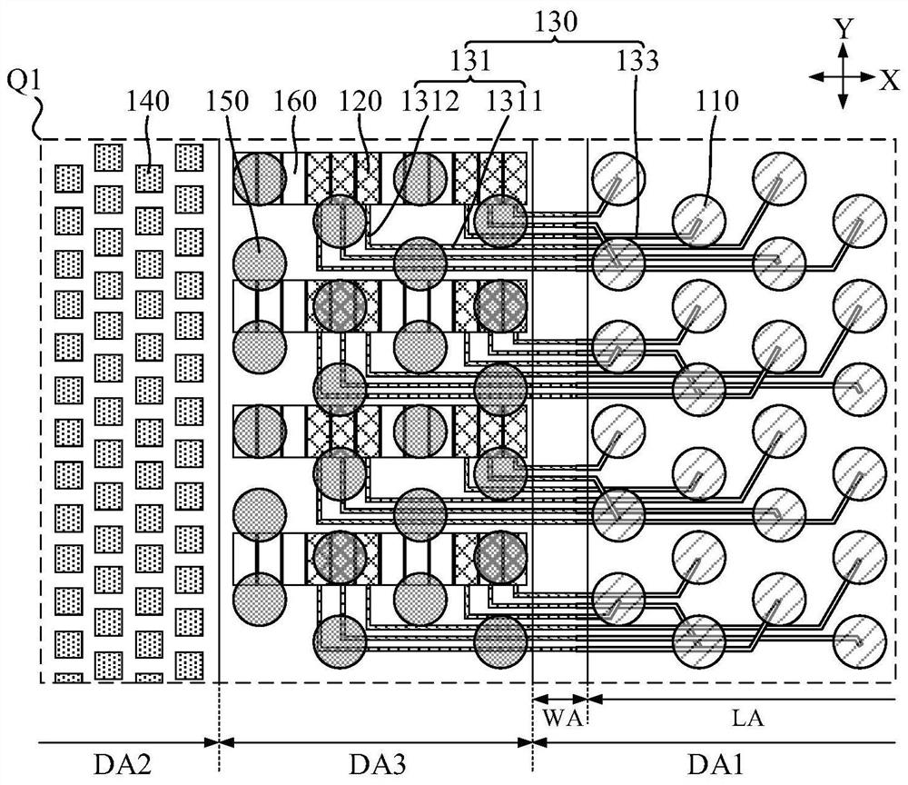
[0004] In the above solution, in order to improve the light-transmitting ability of a part of the display area, the pixel circuit of the light-emitting element used in this part of the display area is usually placed in other part of the display area, and the two are electrically connected through a light-transmitting wire. At this time, the brightness of the light-emitting elements in the two parts of the display area will be different, resulting in uneven display brightness

Method used


Image

  • Display panel and display device
  • Display panel and display device
  • Display panel and display device

Examples


Embodiment Construction

[0028] The characteristics and exemplary embodiments of various aspects of the present invention will be described in detail below. In order to make the purpose, technical solutions and advantages of the present invention clearer, the present invention will be further described in detail below in conjunction with the accompanying drawings and specific embodiments. It should be understood that the specific embodiments described here are only configured to explain the present invention, not to limit the present invention. It will be apparent to one skilled in the art that the present invention may be practiced without some of these specific details. The following description of the embodiments is only to provide a better understanding of the present invention by showing examples of the present invention.

[0029] It should be noted that in this article, relational terms such as first and second are only used to distinguish one entity or operation from another entity or operation...


PUM


Abstract

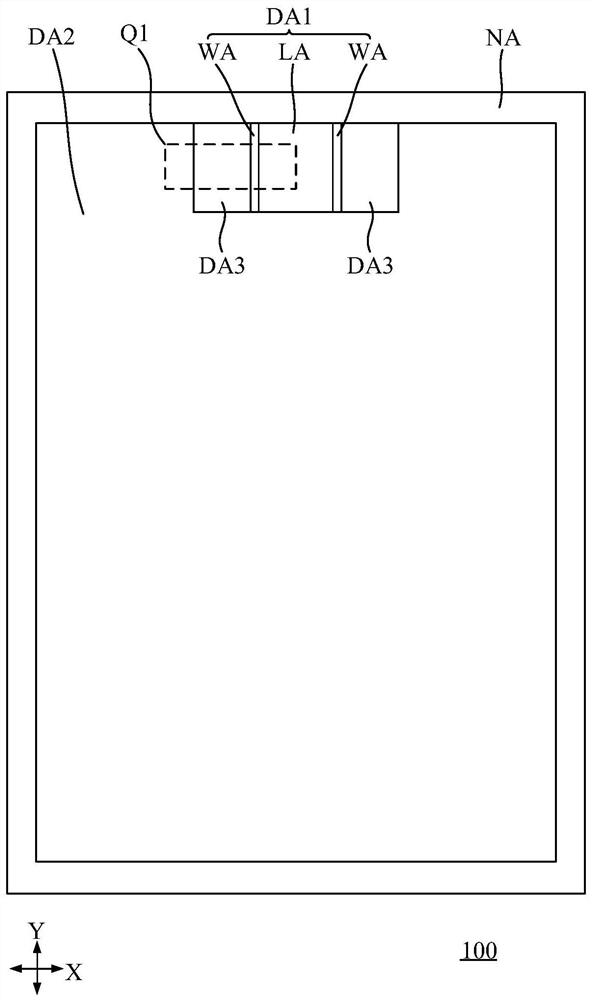
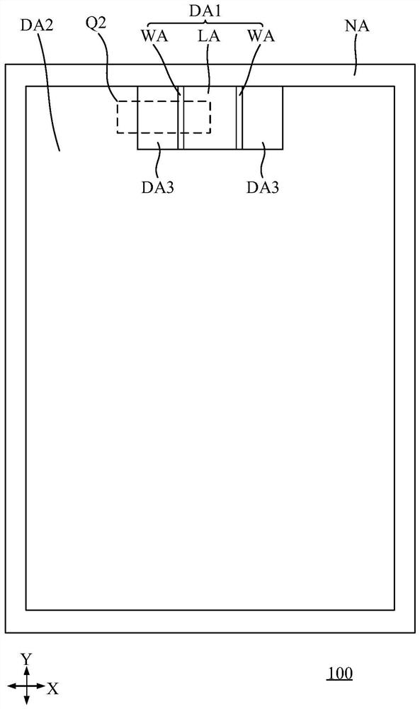
The invention discloses a display panel and a display device. The display panel comprises: a first display area, a second display area and a transition display area, wherein the light transmittance ofthe first display area is larger than that of the second display area, and the first display area comprises an effective light transmitting area and a line changing area located on the peripheral side of the effective light transmitting area; the first light-emitting elements that are arranged in the first display area; the first pixel circuit that is arranged in the transition display area; anda connecting line, wherein the first light-emitting elements located in the effective light-transmitting area are electrically connected with the corresponding first pixel circuits through the connecting lines, each connecting line comprises a first metal line segment and a light-transmitting line segment, the first metal line segments are connected with the first pixel circuits, the light-transmitting line segments are connected with the first light-emitting elements, the first metal line segments extend into the transition display area and extend into the line changing area, the light-transmitting line segment extends to the effective light-transmitting area and extends into the line changing area, and the first metal line and the light-transmitting line segment are connected with each other in the line changing area. According to the display panel provided by the embodiment of the invention, the uniformity of the display brightness of each display area of the display panel is improved.

Description

technical field [0001] The present invention relates to the display field, in particular to a display panel and a display device. Background technique [0002] In electronic devices including display panels, the pursuit of a high screen-to-body ratio with better visual experience has become one of the trends in the development of current display technologies. [0003] Taking mobile phones, tablet computers, etc. as examples, in the current full-screen solution, a part of the display area of ​​the display panel is reused as an integration area of ​​photosensitive elements. At this time, the light transmittance of this part of the display area is relatively high, and photosensitive elements such as front-facing cameras and infrared sensing elements can be arranged on the back of this part of the display area of ​​the display panel, and light can pass through this part of the display area to reach the photosensitive element. Front camera, infrared sensor and other correspondin...

Claims


Application Information

Patent Timeline
Patent Type & Authority Applications(China)
IPC IPC(8): H01L27/32G09G3/3225
CPCG09G3/3225H10K59/60H10K59/65H10K59/131Y02E10/549
Inventor 吴风云向东旭
Owner WUHAN TIANMA MICRO ELECTRONICS CO LTD
Learn More