


Quick Research
Generate reliable direction feasibility study reports for your R&D in just a few steps.

Technical Q&A
Discover and master advanced knowledge NOW. Basics, ideas, possibilities, all at once.

Find Solutions
As an expert in R&D theories, this can generate solutions to your technical problems instantly.

Evaluate Feasibility
Analyze your overall solution with one click, know your potential R&D risks in advance.

Monitor Landscape
Get weekly tech updates, stay abreast of the latest tech innovations and key insights.
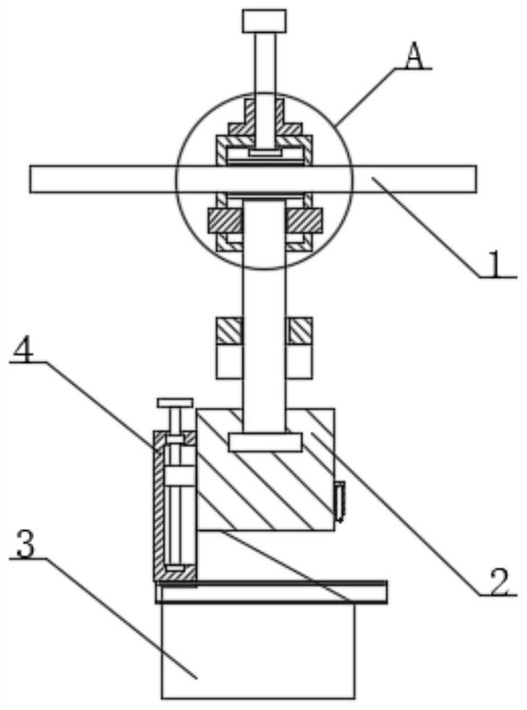
Y-axis positioning structure of rear fixed gauge of bending machine
A positioning structure and bending machine technology, applied in positioning devices, metal processing equipment, feeding devices, etc., can solve the problems of accuracy error, lower product qualification rate, etc., achieve convenience and flexibility, and improve the effect of hemming qualification rate
- Summary
- Abstract
- Description
- Claims
- Application Information
AI Technical Summary
Problems solved by technology
Method used
Image


Examples
Embodiment 1
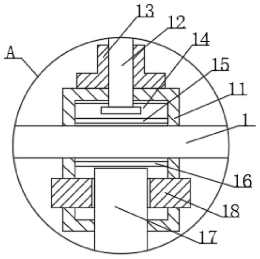
[0026] see Figure 1-6 , the present invention provides a technical solution: a Y-axis positioning structure after a bending machine, including a fixed beam 1 and a Y-axis positioning block 4, the fixed beam 1 is specifically a fixed beam after a bending machine, and the fixed The beam 1 and the bending machine are fixedly connected by bolts, so as to realize the positioning and installation of the fixed beam. The fixed beam 1 has a regular square prism structure, and the outer periphery of the fixed beam 1 is slidingly sleeved with a fixed seat 11. The axis line of the fixed seat 11 in a hollow square prism structure is vertically arranged with the axis line of the fixed beam 1, so as to realize the limitation of the installation orientation of the Y-axis positioning block 4. The middle part of the lower surface of the fixed seat 11 is plugged with a connection Rod 17, the connecting rod 17 has a cylindrical structure, the inner wall of the fixed seat 11 is slidingly sleeved ...
Embodiment 2
[0028] see Figure 1-6, the present invention provides a technical solution: a Y-axis positioning structure after a bending machine, including a fixed beam 1 and a Y-axis positioning block 4, the fixed beam 1 is specifically a fixed beam after a bending machine, and the fixed The beam 1 and the bending machine are fixedly connected by bolts, so as to realize the positioning and installation of the fixed beam. The fixed beam 1 has a regular square prism structure, and the outer periphery of the fixed beam 1 is slidingly sleeved with a fixed seat 11. The axis line of the fixed seat 11 in a hollow square prism structure is vertically arranged with the axis line of the fixed beam 1, so as to realize the limitation of the installation orientation of the Y-axis positioning block 4. The middle part of the lower surface of the fixed seat 11 is plugged with a connection Rod 17, the connecting rod 17 has a cylindrical structure, the inner wall of the fixed seat 11 is slidingly sleeved w...
Embodiment 3
[0030] see Figure 1-6 , the present invention provides a technical solution: a Y-axis positioning structure after a bending machine, including a fixed beam 1 and a Y-axis positioning block 4, the fixed beam 1 is specifically a fixed beam after a bending machine, and the fixed The beam 1 and the bending machine are fixedly connected by bolts, so as to realize the positioning and installation of the fixed beam. The fixed beam 1 has a regular square prism structure, and the outer periphery of the fixed beam 1 is slidingly sleeved with a fixed seat 11. The axis line of the fixed seat 11 in a hollow square prism structure is vertically arranged with the axis line of the fixed beam 1, so as to realize the limitation of the installation orientation of the Y-axis positioning block 4. The middle part of the lower surface of the fixed seat 11 is plugged with a connection Rod 17, the connecting rod 17 has a cylindrical structure, the inner wall of the fixed seat 11 is slidingly sleeved ...
PUM
 Abstract
Description
Claims
Application Information
 - R&D Engineer
- R&D Manager
- IP Professional
- Industry Leading Data Capabilities
- Powerful AI technology
- Patent DNA Extraction
Browse by: Latest US Patents, China's latest patents, Technical Efficacy Thesaurus, Application Domain, Technology Topic, Popular Technical Reports.
© 2024 PatSnap. All rights reserved.Legal|Privacy policy|Modern Slavery Act Transparency Statement|Sitemap|About US| Contact US: help@patsnap.com