
Unmanned aerial vehicle power supply system

A machine power supply system and unmanned aerial vehicle technology, applied in the field of unmanned aerial vehicles, can solve the problems of reducing the inspection efficiency of unmanned aerial vehicles, the impact of power supply system operation and maintenance, resource shortage, etc.

Active Publication Date: 2020-12-29
军事科学院系统工程研究院军事新能源技术研究所
View PDF25 Cites 5 Cited by
  • Summary
  • Abstract
  • Description
  • Claims
  • Application Information

AI Technical Summary

Problems solved by technology

However, due to inconvenient transportation and complex terrain in these areas, it is difficult to deliver the power energy of the power grid or the voltage of the power grid delivered is unstable. machine inspection efficiency
Therefore, it is necessary to obtain power energy through local resources, but border areas are short of resources. How to realize the energy self-sufficiency of the frontier power supply system through limited resources and ensure the power supply of drones is also a major problem to be solved.
In addition, in border areas with harsh environments, the operation and maintenance of the power supply system will be greatly affected by the environment, resulting in repeated reductions in the charging efficiency of drones. Ensuring the safe and stable operation of the power supply system is another problem that needs to be solved urgently

Method used


Image

  • Unmanned aerial vehicle power supply system
  • Unmanned aerial vehicle power supply system
  • Unmanned aerial vehicle power supply system

Examples


Embodiment Construction

[0076] The following will clearly and completely describe the technical solutions in the embodiments of the present specification in combination with the drawings in the embodiments of the present specification. Obviously, the described embodiments are only some of the embodiments of the present specification, not all of them. Based on the embodiments in this specification, all other embodiments obtained by persons of ordinary skill in the art without making creative efforts fall within the protection scope of this specification.

[0077] It should be noted that the terms "include" and "have" in the embodiments of this specification and the drawings, as well as any variations thereof, are intended to cover non-exclusive inclusion. For example, a process, method, system, product or device comprising a series of steps or units is not limited to the listed steps or units, but optionally also includes unlisted steps or units, or optionally further includes For other steps or units...


PUM


Abstract

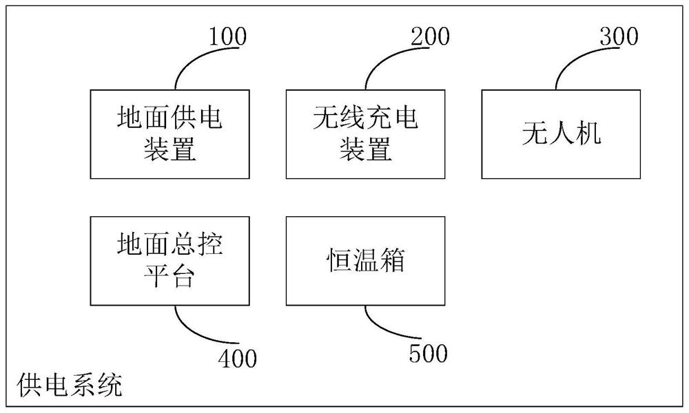
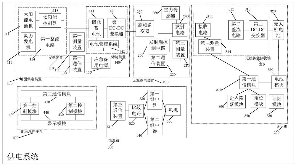
An embodiment of the invention discloses an unmanned aerial vehicle power supply system. The system comprises a ground power supply device, a wireless charging device, an unmanned aerial vehicle, a ground master control platform and a thermostat, wherein the ground power supply device is used for converting wind energy and solar energy into electric energy, storing the electric energy into an energy storage battery and supplying power to the wireless charging device through the energy storage battery; the wireless charging device is used for charging the unmanned aerial vehicle parked at a charging position through a transmitting circuit; the unmanned aerial vehicle is used for receiving a charging instruction sent by the ground master control platform and going to the charging position onthe designated wireless charging device for charging according to the charging instruction; the ground master control platform is used for acquiring state information of the ground power supply device, the wireless charging device and the unmanned aerial vehicle and sending the charging instruction to the unmanned aerial vehicle according to the state information; and the thermostat is used for maintaining the battery temperature of the unmanned aerial vehicle within a preset temperature range according to the battery temperature of the unmanned aerial vehicle being charged.

Description

technical field [0001] This specification relates to the technical field of unmanned aerial vehicles, and in particular, relates to a power supply system for unmanned aerial vehicles. Background technique [0002] Since drones can reach places that inspection personnel cannot or are inconvenient to reach, complete time-consuming and labor-intensive work safely and efficiently, and liberate inspection personnel from high-risk environments and high-intensity physical labor, drones are gradually used. To complete some preset tasks such as reconnaissance and patrol inspection. [0003] However, some drones are used in remote border areas, where transportation is inconvenient, sparsely populated, and the environment is harsh. Due to the sparsely populated border areas and dangerous geographical terrain, it is difficult for staff to replace batteries for drones. For this reason, the drone's power supply system can be used to realize autonomous charging of drones. However, due to...

Claims


Application Information

Patent Timeline
IPC IPC(8): B60L53/12B60L53/38B60L53/22B60L53/30B60L53/52B60L53/51B60L53/62H02J7/00H02J7/35H02J50/12H02J50/80H02J50/90B64C39/02B64F1/00
CPCB60L53/12B60L53/38B60L53/22B60L53/30B60L53/52B60L53/51B60L53/62H02J7/35H02J7/0047H02J7/007194H02J50/12H02J50/80H02J50/90B64C39/02B64F1/00B60L2200/10Y02T90/12
Inventor 王旭东王长富鲁长波徐万里刘盼盼周友杰安高军陈今茂王耀辉徐曦萌孙彦丽郑哲
Owner 军事科学院系统工程研究院军事新能源技术研究所
Learn More