
fan

A fan and fan frame technology, applied in the field of fans that can produce glare visual effects, can solve the problems of waste, difficult disassembly by users, etc., so as to improve the convenience of use, easy assembly or disassembly and replacement, and simple and fast assembly operations. Effect

Active Publication Date: 2022-08-05
SUNON ELECTRONICS KUNSHAN
View PDF10 Cites 0 Cited by
  • Summary
  • Abstract
  • Description
  • Claims
  • Application Information

AI Technical Summary

Problems solved by technology

[0004] However, although the existing fans can achieve heat dissipation and glare effects, the plurality of light-emitting elements are fixedly arranged on the fan frame, and it is difficult for users to disassemble and replace them by themselves, so that the light color and glare produced by the fan The effects are all the same. In the pursuit of novelty, consumers can only choose to re-purchase other fans with different glare effects, which will lead to unnecessary waste.

Method used


Image

  • fan
  • fan
  • fan

Examples


Embodiment Construction

[0072] In order to make the above-mentioned and other objects, features and advantages of the present invention more obvious and easy to understand, the preferred embodiments of the present invention are enumerated below, and are described in detail as follows in conjunction with the accompanying drawings:

[0073] Directionality or similar terms used throughout this disclosure, such as "front", "rear", "left", "right", "top (top)", "bottom (bottom)", "inside", "outside" , "side surface", etc., mainly refer to the directions of the drawings, and each directionality or its similar terms are only used to assist the description and understanding of the various embodiments of the present invention, and are not intended to limit the present invention.

[0074] The use of the quantifier "a" or "an" for the elements and components described throughout the present invention is only for convenience of use and provides a general meaning of the scope of the present invention; in the prese...


PUM


Abstract

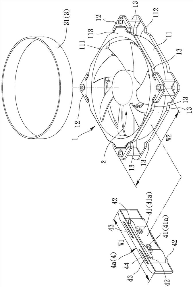
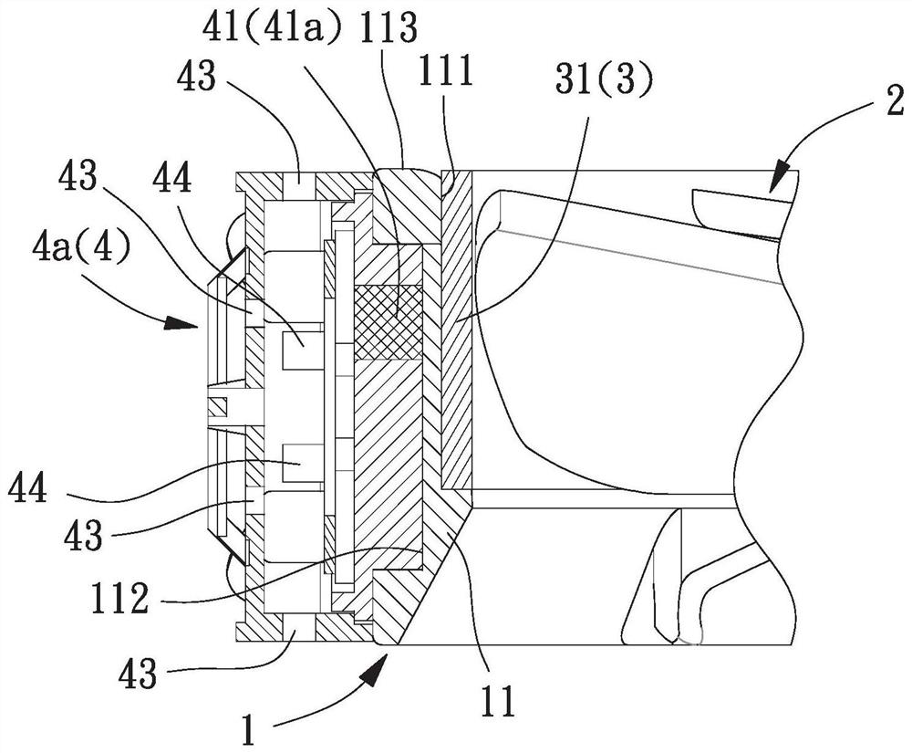
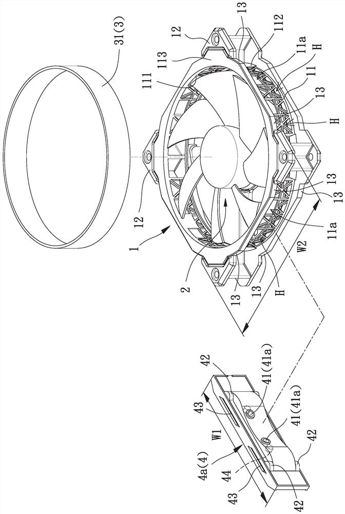
A fan is used to solve the problem that the existing fans are difficult to replace the light-emitting group according to their own preferences, which comprises: a fan frame with a ring wall; a fan wheel rotatably arranged on the fan frame; , located in the ring wall, the ornament ring has at least one first magnetic attraction part; and a light-emitting group has at least one second magnetic attraction part, the light-emitting group passes through the second magnetic attraction part and the first magnetic attraction part of the ornament ring The magnetic attraction part is magnetically attracted and combined with the fan frame.

Description

technical field [0001] The invention relates to a fan, in particular to a fan capable of producing glare visual effects. Background technique [0002] In addition to the existing cooling effect of the existing fan, in order to increase the aesthetics of the fan when it operates, light-emitting diodes are more widely used and combined in the fan, so that the fan can generate a dazzling visual effect while running, and then It can increase the added value of the product and increase the willingness of consumers to buy. [0003] The existing fan has a fan frame and a fan wheel, the fan frame can be assembled and positioned by a plurality of light-emitting elements and at least one light-homing element, and the at least one light-homing element is aligned with the plurality of light-emitting elements, so that the plurality of light-emitting elements can be aligned. The light generated by the light-emitting element can be projected through the at least one light homogenizer; the...

Claims


Application Information

Patent Timeline
Patent Type & Authority Patents(China)
IPC IPC(8): F04D25/08F04D29/00F04D29/52F21V33/00
CPCF04D25/08F04D29/005F04D29/522F21V33/0096
Inventor 洪银树蔡佳景周泓澄
Owner SUNON ELECTRONICS KUNSHAN
Learn More