Low-voltage power distribution cabinet

A low-voltage power and power distribution cabinet technology, which is applied in substation/power distribution device casing, electrical components, substation/switch layout details, etc., can solve the problem of circuit failure of power distribution cabinet, inconvenient disassembly, easy temperature rise of power distribution cabinet, etc. problem, to achieve fast installation and lifting, fast installation and disassembly, and solve the effect of poor temperature control and adjustment ability

Active Publication Date: 2020-12-18
SHANDONG TAILAI ELECTRIC
View PDF4 Cites 0 Cited by
  • Summary
  • Abstract
  • Description
  • Claims
  • Application Information

AI Technical Summary

Problems solved by technology

[0003] At present, there are many types of power distribution cabinets on the market, but this kind of power distribution cabinet needs to build a cement base on the ground in the process of use. Once this kind of device is fixed, it is difficult to take it out here, and it is inconvenient to disassemble. At the same time, during the use of the existing devices, the internal temperature of the power distribution cabinet is easy to rise, which often leads to different temperatures inside and outside the power distribution cabinet, making it easy to accumulate water mist inside the power distribution cabinet, which in turn leads to The internal circuit is faulty. In addition, the electric meter inside the existing device is not easy to disassemble and install during the maintenance process. Therefore, we propose a low-voltage power distribution cabinet

Method used


Image

  • Low-voltage power distribution cabinet
  • Low-voltage power distribution cabinet
  • Low-voltage power distribution cabinet

Examples


Embodiment Construction

[0024] The following will clearly and completely describe the technical solutions in the embodiments of the present invention with reference to the accompanying drawings in the embodiments of the present invention. Obviously, the described embodiments are only some, not all, embodiments of the present invention.

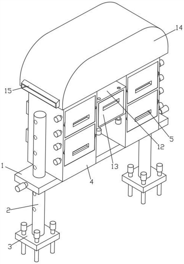
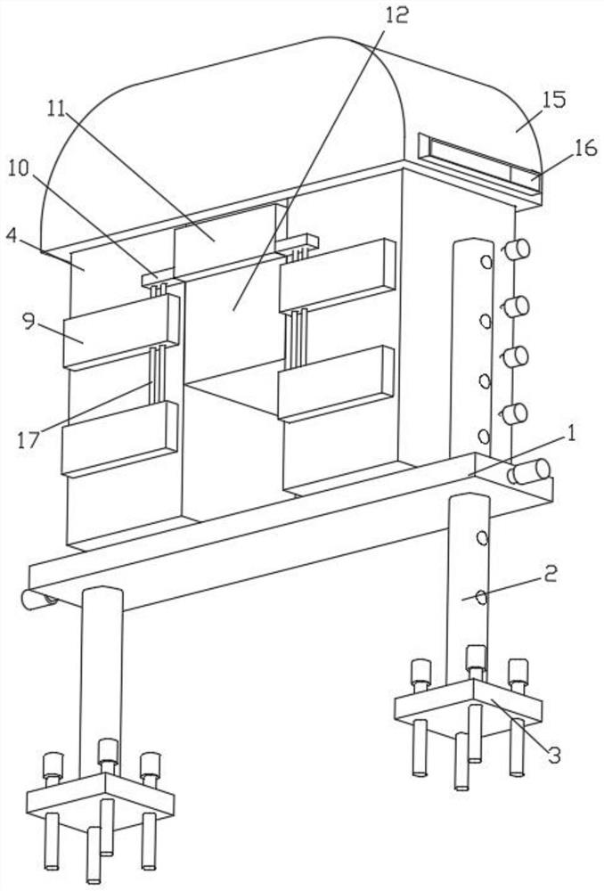
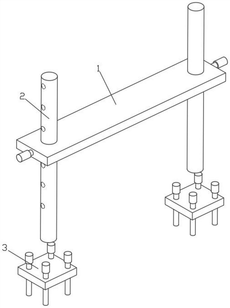
[0025] see Figure 1 to Figure 6, the present invention provides a technical solution: a low-voltage power distribution cabinet, including a bottom plate 1, the interior of the bottom plate 1 is provided with symmetrically distributed circular holes, and the circular holes inside the bottom plate 1 are movably connected with relatively distributed main piles 2. There are symmetrically distributed cylindrical holes on both sides of the exterior of the bottom plate 1, and the inner walls of the cylindrical holes on both sides of the exterior of the bottom plate 1 are provided with threaded grooves, and the threaded grooves on both sides of the exterior of the bottom pla...


PUM


Abstract

The invention discloses a low-voltage power distribution cabinet, and relates to the technical field of power distribution cabinets, in particular to a low-voltage power distribution cabinet, which comprises a bottom plate, circular holes which are symmetrically distributed are formed in the bottom plate, main piles which are oppositely distributed are movably connected to the circular holes in the bottom plate, and fixed bases are fixedly connected to the bottom ends of the main piles. According to the low-voltage power distribution cabinet, the symmetrically-distributed circular holes are formed in the bottom plate, the fixing nuts which are oppositely distributed are in threaded connection with the two sides of the outer portion of the bottom plate, the symmetrically-distributed main piles are movably connected into the circular holes in the bottom plate, and meanwhile the fixing bases are fixedly connected to the bottom ends of the main piles; by means of the notch formed in the outer portion of the main pile and the nut in the fixing base, it can be guaranteed that the device can be rapidly installed and lifted, and the problems that an existing device can only be fixedly connected to a cement base and is inconvenient to disassemble are solved.

Description

technical field [0001] The invention relates to the technical field of power distribution cabinets, in particular to a low-voltage power distribution cabinet. Background technique [0002] The low-voltage power distribution cabinet market has maintained a rapid growth trend with the implementation of smart grids, infrastructure construction, investment in the manufacturing industry, and the development of the new energy industry. Therefore, for the construction of construction sites, mines, and urbanization, people A low-voltage power distribution cabinet is needed. [0003] At present, there are many types of power distribution cabinets on the market, but this kind of power distribution cabinet needs to build a cement base on the ground in the process of use. Once this kind of device is fixed, it is difficult to take it out here, and it is inconvenient to disassemble. At the same time, during the use of the existing devices, the internal temperature of the power distributi...

Claims


Application Information

Patent Timeline
IPC IPC(8): H02B1/30H02B1/32H02B1/50H02B1/56H02B1/03H02B1/28
CPCH02B1/30H02B1/303H02B1/50H02B1/505H02B1/565H02B1/32H02B1/03H02B1/28
Inventor 李红
Owner SHANDONG TAILAI ELECTRIC
Why Eureka
Try Eureka