
Transmitted waveform optimization method based on linear frequency modulation signal approximation expected power spectrum

A technology of linear frequency modulation signal and transmission waveform, applied in the field of radar, can solve the problems of difficult to meet the real-time requirements of radar, slow optimization speed, large amount of calculation, etc., and achieve good quality of transmitted signal, fast optimization speed, and small amount of calculation Effect

Pending Publication Date: 2020-12-18
XIDIAN UNIV +1
View PDF0 Cites 0 Cited by
  • Summary
  • Abstract
  • Description
  • Claims
  • Application Information

AI Technical Summary

Problems solved by technology

[0004] However, the above methods require a large amount of calculation and slow optimization speed, making it difficult to meet the real-time requirements of radar

Method used


Image

  • Transmitted waveform optimization method based on linear frequency modulation signal approximation expected power spectrum
  • Transmitted waveform optimization method based on linear frequency modulation signal approximation expected power spectrum
  • Transmitted waveform optimization method based on linear frequency modulation signal approximation expected power spectrum

Examples


Embodiment 1

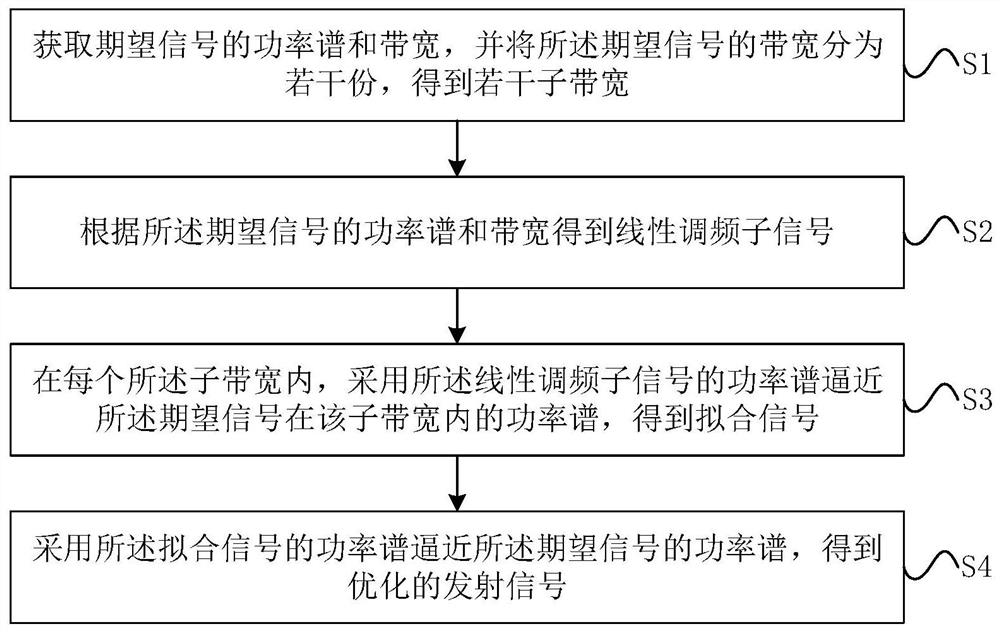
[0048]Seefigure 1 ,figure 1 It is a method for optimizing the transmitted waveform based on the chirp signal approaching the expected power spectrum provided by the embodiment of the present invention, including:

[0049]S1: Obtain the power spectrum and bandwidth of the desired signal, and divide the bandwidth of the desired signal into several parts to obtain several sub-bandwidths, including:

[0050]First, the power spectrum of a given desired signal is P0, The bandwidth is B0.

[0051]Then, according to the principle of equal energy division, the bandwidth of the desired signal is divided into several sub-bandwidths. Specifically, according to the principle of equal division of energy, the bandwidth of the desired signal is divided into N parts of bandwidth B1,B2,...,BN, And meet

[0052]S2: Obtain the chirp sub-signal according to the power spectrum and bandwidth of the desired signal.

[0053]Specifically, first obtain the total energy of the desired signal according to the power spectrum a...

Embodiment 2

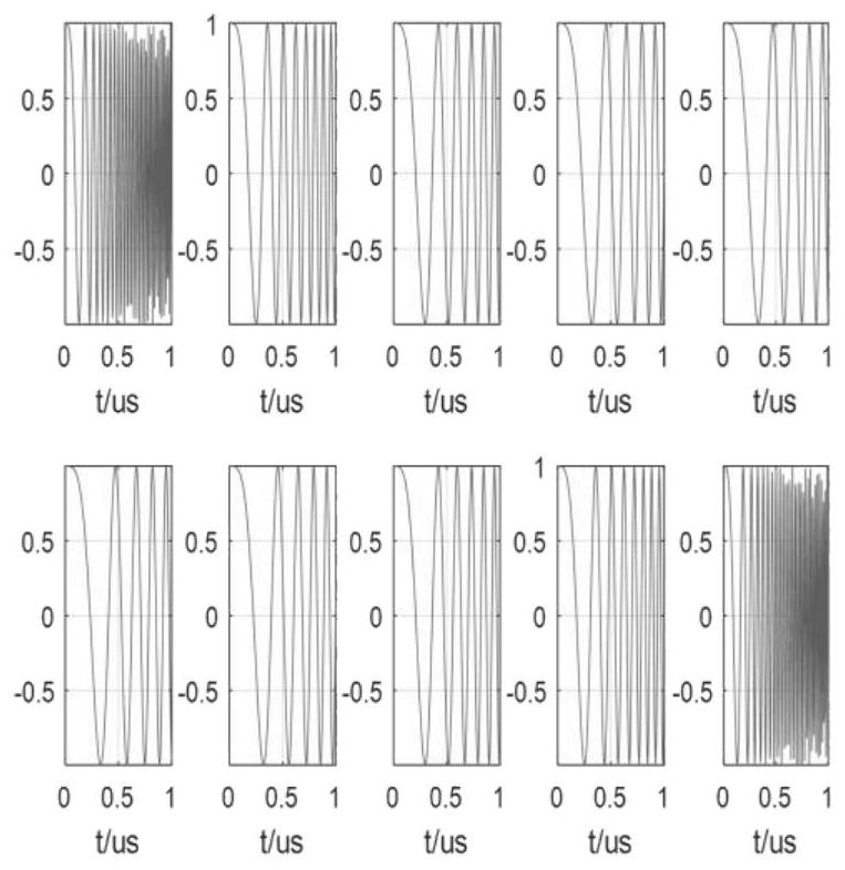
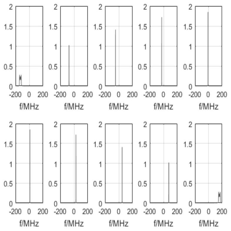
[0087]In the following, simulation experiments are used to further illustrate the effect of the transmission waveform optimization method based on the chirp signal approaching the desired power spectrum provided in the first embodiment.


PUM


Abstract

The invention discloses a transmitted waveform optimization method based on a linear frequency modulation signal approximation expected power spectrum; and the method comprises the steps: obtaining the power spectrum and bandwidth of an expected signal, dividing the bandwidth of the expected signal into a plurality of parts, and obtaining a plurality of sub-bandwidths; obtaining a linear frequencymodulation sub-signal according to the power spectrum and the bandwidth of the expected signal; in each sub-bandwidth, using the power spectrum of the power spectrum approximation expected signal ofthe non-linear frequency modulation sub-signal, and obtaining a fitting signal; and using the power spectrum of the power spectrum approximation expected signal of the fitting signal to obtain an optimized transmitting signal. The transmitted waveform optimization method based on linear frequency modulation signal approximation expected power spectrum provided by the invention is good in approximation degree, the obtained optimized transmitted signal is good in quality, the process is small in calculated amount and high in optimization speed, and the requirement of radar on real-time performance can be met.

Description

Technical field[0001]The invention belongs to the technical field of radar, and specifically relates to a method for optimizing transmission waveforms based on a chirp signal approaching a desired power spectrum.Background technique[0002]Radar is an electronic device that uses radio to find targets and determine their spatial position. With the development of radar technology, radar systems have been widely used in many fields in military and civilian use. Traditional radar generally has a directional narrow beam. In order to ensure that all targets in the desired airspace can be effectively detected, a narrow beam is required to scan in the airspace quickly and reciprocally; for detected targets, the beam pointing can be adjusted according to the movement of the target for target tracking; or The discovered target emits a specific signal for radar imaging, target classification and recognition. According to the needs of multitasking and the variability of actual scenes, a radar is ...

Claims


Application Information

Patent Timeline
Patent Type & Authority Applications(China)
IPC IPC(8): G01S7/282G01S7/35
CPCG01S7/282G01S7/35Y02D30/70
Inventor 纠博杨宇高青松黄金杰谢少鹏
Owner XIDIAN UNIV
Learn More