
Driving roller locking structure

A technology of locking structure and driving roller, which is applied in the direction of transmission parts, rollers, conveyor objects, etc., can solve problems such as imperfect structure of the device, achieve the effects of preventing accidental breakage, improving performance, and simple operation

Active Publication Date: 2020-12-18
芜湖韩保光学新材料有限公司
View PDF9 Cites 2 Cited by
  • Summary
  • Abstract
  • Description
  • Claims
  • Application Information

AI Technical Summary

Problems solved by technology

[0004] Aiming at the deficiencies of the prior art, the present invention provides a driving roller locking structure, which solves the problem of imperfect structure of the existing device

Method used


Image

  • Driving roller locking structure
  • Driving roller locking structure
  • Driving roller locking structure

Examples


Embodiment Construction

[0027] The following will clearly and completely describe the technical solutions in the embodiments of the present invention with reference to the accompanying drawings in the embodiments of the present invention. Obviously, the described embodiments are only some, not all, embodiments of the present invention. Based on the embodiments of the present invention, all other embodiments obtained by persons of ordinary skill in the art without making creative efforts belong to the protection scope of the present invention.

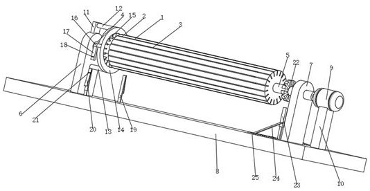
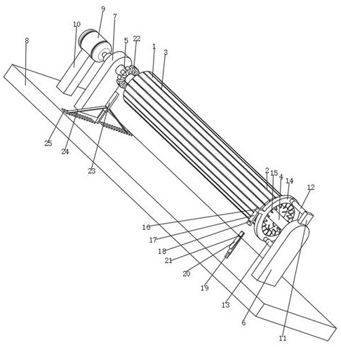
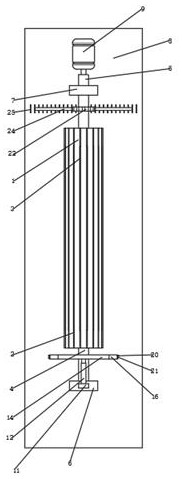
[0028] see Figure 1-5 , the present invention provides a technical solution: a driving roller locking structure, which is simple to operate and has strong practicability. The rubber strip 3 is fixedly connected, and the use of the rubber strip 3 strengthens the thermal expansion and contraction function of the transmission roller main body 1, and improves the performance of the transmission roller main body 1. The left side of the transmission roller main bod...


PUM


Abstract

The invention discloses a driving roller locking structure. The driving roller locking structure comprises a driving roller main body, groove strips are formed in the outer side of the driving rollermain body at equal intervals, a left rotating shaft is fixedly connected to the left side of the driving roller main body, and a right rotating shaft is fixedly connected to the right side of the driving roller main body. The driving roller locking structure is easy to operate and high in practicability, the left rotating shaft, the right rotating shaft, a left supporting plate, a right supportingplate, a bottom plate, a rotating motor and a bottom block are used for providing rotating force for the driving roller main body, and verification of the function of the locking structure is facilitated; a top block body, an upper telescopic rod, a lower telescopic rod, a circular ring body, an inserting strip, a connecting strip, an inserting pipe, a clamping hole, a telescopic inserting rod, an elastic strip and a clamping block are used for locking and fixing of the driving roller main body; a clamping ring body, a telescopic clamping rod, a clamping column and a clamping block are used for further locking and fixing of the driving roller main body; and the upper telescopic rod and the lower telescopic rod are used for vertical clamping of the circular ring body, the clamping column is used, accidental breakage of the telescopic clamping rod is prevented, and the supporting performance of the telescopic clamping rod is enhanced.

Description

technical field [0001] The invention relates to the technical field of drive rollers, in particular to a drive roller locking structure. Background technique [0002] As a common mechanical structure, the transmission roller is widely used in various mechanical structures. As a transmission roller, it often uses its own rotation characteristics to perform some transmission and transportation tasks. The existing transmission rollers are often Some locking structures are needed to fix the transmission rollers, so as to realize stable control of transmission and conveying, but the existing locking devices have poor locking effect and cannot effectively lock the transmission rollers. Contents of the invention [0003] (1) Solved technical problems [0004] Aiming at the deficiencies of the prior art, the present invention provides a driving roller locking structure, which solves the problem of imperfect structure of the existing device. [0005] (2) Technical solution [00...

Claims


Application Information

Patent Timeline
IPC IPC(8): F16C13/00F16H57/00B65G39/02B65G39/12
CPCB65G39/02B65G39/12F16C13/006F16H57/0037
Inventor 徐兵
Owner 芜湖韩保光学新材料有限公司
Learn More