
Noise reduction device and method and outdoor direct-current charging pile using noise reduction device

A technology of noise reduction and air outlet device, which is applied in the components of pumping device for elastic fluid, charging station, electric vehicle charging technology, etc., can solve the problem of temporary deafness of field maintenance personnel, poor charging of field users, noise Pollution and other problems, to achieve the effect of significant noise reduction, less disturbance to residents, and low cost

Pending Publication Date: 2020-12-18
SHIJIAZHUANG TONHE ELECTRONICS TECH CO LTD
View PDF3 Cites 1 Cited by
  • Summary
  • Abstract
  • Description
  • Claims
  • Application Information

AI Technical Summary

Problems solved by technology

[0006] In order to solve the noise pollution and nuisance when the outdoor DC charging pile in the above-mentioned prior art is in operation, especially the noise during night work reported by the residents is particularly prominent, the on-site maintenance personnel will be temporarily deaf, and the on-site users will be charged. The main purpose of the present invention is to provide a noise reduction device and an outdoor DC charging pile using the device to solve the above background and existing problems and deficiencies

Method used


Image

  • Noise reduction device and method and outdoor direct-current charging pile using noise reduction device
  • Noise reduction device and method and outdoor direct-current charging pile using noise reduction device
  • Noise reduction device and method and outdoor direct-current charging pile using noise reduction device

Examples


Embodiment Construction

[0035] The technical solutions of the present invention will be further specifically described below through embodiments and in conjunction with the accompanying drawings.

[0036] In order to clearly describe a noise reduction device and method of the present invention and an outdoor DC charging pile using the device, a specific embodiment is given to illustrate it.

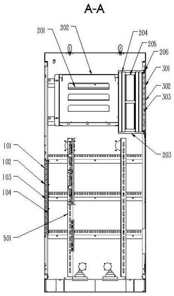
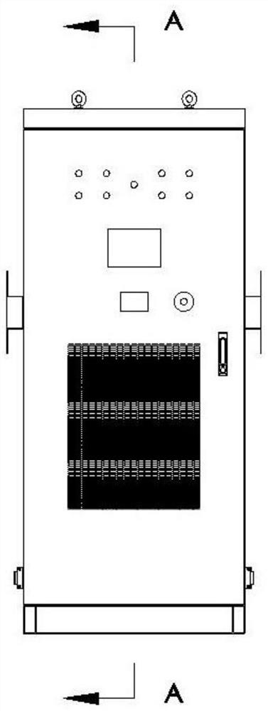
[0037] In this specific example, see Figure 1- Figure 8 ,in, Figure 1a , Figure 1b It is the overall structure of an outdoor DC charging pile and its A-direction sectional view of the present invention. figure 2 It is a three-dimensional exploded schematic view of the air inlet device part of the present invention. Figure 3a , Figure 3b It is a front view of a kind of air inlet device of the present invention and its B-direction sectional schematic diagram (can refer to figure 2 three-dimensional schematic structure). Figure 4 It is a schematic diagram of the internal decomposition of the noise redu...


PUM


Abstract

The invention provides a noise reduction device and method and an outdoor direct-current charging pile using the device. Air sequentially enters a front air inlet buffer part from an air inlet device,an air duct of a noise reduction process device and an internal charging module of the noise reduction process device, is output to an air outlet buffer part through a draught fan serving as airflowdirection source power, and then is exhausted through an air outlet device. Meanwhile, after passing through the air inlet buffer part, the airflow is weakened through a first-stage sieve pore plate and then enters a second-stage concave pore plate, collision and buffering are generated, sound waves interfere with one another, the airflow speed is reduced. In addition, sound absorption cotton is attached to the inner walls of the buffer parts, and the airflow enters a third-stage sieve pore plate after being weakened again and then enters the draught fan after being further weakened. The weakened airflow is sucked into the draught fan through air draft and is discharged to the air outlet buffer part. Similarly, after passing through the air outlet buffer part, the airflow is weakened by buffer sound waves and further weakened through the air outlet device. Noise pollution is reduced by the aid of the noise reduction device, and disturbance to residents, poor user experience and temporary deafness of field personnel in operation and maintenance are reduced.

Description

technical field [0001] The invention relates to the field of electric vehicle charging piles, in particular to an outdoor DC charging pile with a noise reduction method and device and the device. Background technique [0002] In order to ensure the long-term stable operation of the outdoor DC charging pile during operation, the structure is equipped with a cooling fan to reduce the heat of internal components to prevent damage. But at the same time, the fans generate noise pollution, which disturbs the residents, especially at night, when the noise is more obvious. In addition, it also brings "buzzing" noise and bad experience to the on-site charging personnel and maintenance personnel. Usually, the main source of noise is the noise of the cooling fan. [0003] In order to solve the above problems, people in the field have made unremitting efforts, for example, the patent of Chinese Patent Publication No. CN105142379 A, ​​which discloses a noise reduction cabinet. In addi...

Claims


Application Information

Patent Timeline
IPC IPC(8): F04D29/66F04D29/70G10K11/162B60L53/31B60L53/302
CPCF04D29/663F04D29/664F04D29/665F04D29/701G10K11/162B60L53/31B60L53/302Y02T10/70Y02T10/7072Y02T90/12
Inventor 刘峰于红亮车磊刘亚光李欢冯亚森唐光伟吴彦
Owner SHIJIAZHUANG TONHE ELECTRONICS TECH CO LTD
Learn More