Railway steel rail drilling machine

A drilling machine and rail technology, applied in the field of drilling machines, can solve the problems of wasting manpower, wasting staff time, wasting rails, etc., and achieving the effects of increasing work efficiency, saving labor, and increasing accuracy

Inactive Publication Date: 2020-12-18
杨丽红
View PDF7 Cites 2 Cited by
  • Summary
  • Abstract
  • Description
  • Claims
  • Application Information

AI Technical Summary

Problems solved by technology

[0003] At present, the existing rails are drilled, and portable electric drills are mostly used to drill the rails. After drilling a hole, it needs to be repositioned, which wastes a lot of time for the staff. Deviations are prone to occur during drilling, resulting in waste of rails. The equipment is laborious in the process of moving and drilling, and needs manual handling, which wastes a lot of manpower

Method used


Image

  • Railway steel rail drilling machine
  • Railway steel rail drilling machine
  • Railway steel rail drilling machine

Examples


Embodiment 1

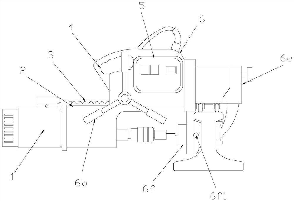
[0032] see Figure 1-Figure 6 , the present invention provides a railway rail drilling machine, the structure of which includes a drilling machine 1, a slide bar 2, a gear bar 3, a handle 4, an operation panel 5, and a mounting frame 6, and the top of the drilling machine 1 is A slide bar 2 is provided, the drilling machine 1 and the slide bar 2 are an integrated structure, the top of the slide bar 2 is provided with a gear bar 3, and the described slide bar 2 and the gear bar 3 are fixedly connected, and the The top of the drilling machine 1 is provided with a mounting frame 6, the drilling machine 1 and the mounting frame 6 are slidingly connected by a slide bar 2, and the top of the mounting frame 6 is provided with a handle 4. The installation frame 6 and the handle 4 are integrated structures, and the operation panel 5 is installed on the surface of the installation frame 6;

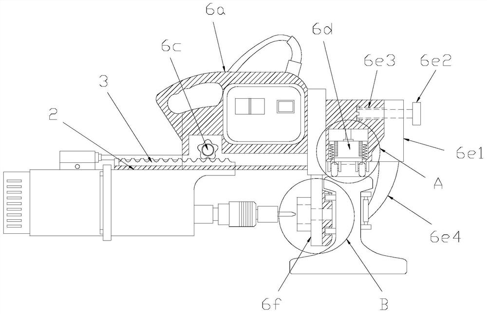
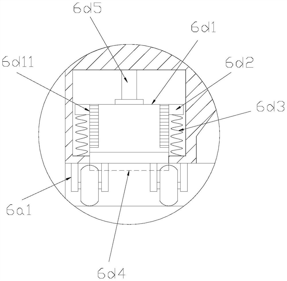
[0033]Described installation frame 6 is made up of body 6a, propulsion handwheel lever 6b, tran...

Embodiment 2

[0042] see Figure 1-Figure 6 , the present invention provides a railway rail drilling machine, the guide mechanism 6f is composed of a telescopic positioning rod 6f1, a fixed plate 6f2, a balance limit sleeve 6f3, a second perforation 6f4, and a third pulley 6f5. Telescopic positioning rods 6f1 are installed on the front and rear ends of the plate 6f2, and the left side of the fixed plate 6f2 is provided with a balance limit sleeve 6f3, and the fixed plate 6f2 is fixedly connected with the balance limit sleeve 6f3. A second perforation 6f4 is provided in the middle of the surface of the fixed plate 6f2, and four third pulleys 6f5 are equidistantly distributed on the right side surface of the fixed plate 6f2, and the fixed plate 6f2 and the third pulley 6f5 adopt a gap Cooperate.

[0043] One end of the telescopic positioning rod 6f1 is provided with a finger hole head 6f11, and the telescopic positioning rod 6f1 and the finger hole head 6f11 are welded by electric welding. ...


PUM


Abstract

The invention discloses a railway steel rail drilling machine. The railway steel rail drilling machine structurally comprises a drill, a sliding strip, a gear strip, a handle, an operation panel and amounting rack. The mounting rack is composed of a machine body, a propelling hand wheel rod, a transmission gear, a positioning mechanism, a clamping mechanism and a guiding mechanism. The mounting rack is arranged on the surface of a steel rail through the clamping mechanism, so that the drill does not shake in the drilling process. Besides, the mounting rack can be positioned on the steel railthrough the positioning mechanism, so that the precision of the drill in the drilling process is improved. Through the mutual cooperation of first pulleys, second pulleys and third pulleys, constructors do not need to carry and move the drill for drilling of a next hole, so that the labor force of the constructors is saved, and the working efficiency of the constructors is improved. The mounting rack prevents the drill from deviating and derailing during drilling through the guiding mechanism, and drilling positions are rapidly and accurately determined through hole pointing heads on telescopic positioning rods.

Description

technical field [0001] The invention relates to the field of drilling machines, in particular to a railway rail drilling machine. Background technique [0002] Railway tracks, referred to as rails, rails, tracks, etc., are used on railways and cooperate with switchers to allow trains to walk without turning. The track is usually composed of two parallel steel rails. The rails are fixed on the sleepers, and the ballast is under the sleepers. The rails made of steel can bear greater weight than other materials. Sleepers, also known as sleepers, or road sleepers, function to separate and distribute the weight of the rails, keep the rails fixed, and maintain the gauge of the rails. Generally speaking, the bottom of the track is paved with gravel ballast, also known as ballast, crushed stone or ballast bed, which provides elasticity and drainage for the track. Tracks can also be laid on concrete bases (quite common on bridges) or even embedded in concrete. Railway tracks must ...

Claims


Application Information

Patent Timeline
Patent Type & Authority Applications(China)
IPC IPC(8): E01B31/06
CPCE01B31/06E01B2203/012
Inventor 杨丽红
Owner 杨丽红
Why Eureka
Try Eureka