
Gear box jointly driven by winch and turntable

A technology of gear boxes and turntables, which is applied in hoisting devices, spring mechanisms, etc., can solve the problems of complex structure of the drill shaft, large volume of the gearbox, and large space occupation, and achieve good drilling characteristics, high transmission efficiency, Overall weight reduction effect

Active Publication Date: 2020-12-11
中油国家油气钻井装备工程技术研究中心有限公司 +2
View PDF14 Cites 1 Cited by
  • Summary
  • Abstract
  • Description
  • Claims
  • Application Information

AI Technical Summary

Problems solved by technology

[0004] The purpose of the present invention is to provide a winch turntable joint drive gearbox, which solves the problem of the low efficiency of the combined drive of the existing turntable and drawworks, and the large space and high cost of driving the turntable and drawworks alone; The problem with the large volume of the box

Method used


Image

  • Gear box jointly driven by winch and turntable
  • Gear box jointly driven by winch and turntable
  • Gear box jointly driven by winch and turntable

Examples


Embodiment Construction

[0020] The present invention will be described in detail below in conjunction with the accompanying drawings and specific embodiments.

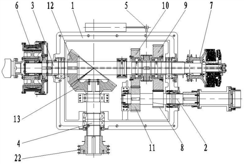
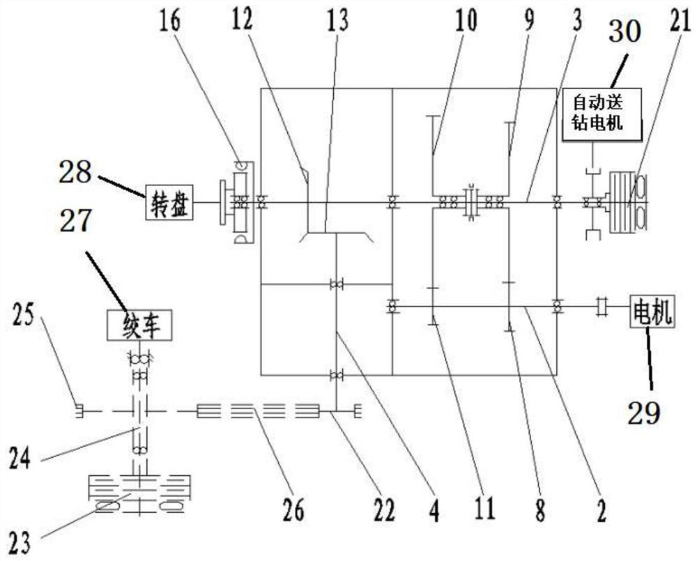
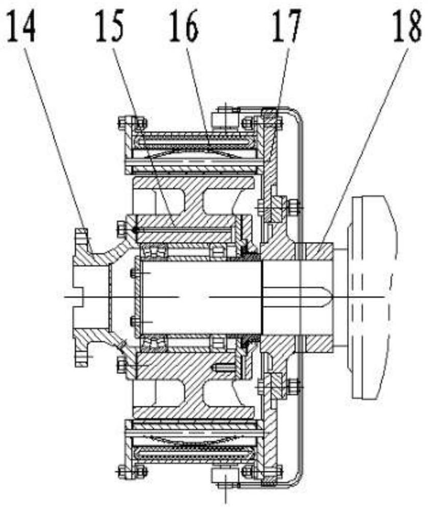
[0021] refer to figure 1 , figure 2 , image 3 with Figure 4 , the structure of the device of the present invention is to include a box body 1, the box body 1 is equipped with an input shaft assembly 2, an intermediate shaft assembly 3 and an output shaft assembly 4 through a bearing seat, and the three shaft assemblies are connected by gears Engagement transmits power and torque;

[0022] The input shaft assembly 2 is connected with the motor 29 to provide power for the entire gearbox. The input shaft assembly 2 is coaxially fixed with a spur gear I8 and a spur gear IV11, and both the spur gear I8 and the spur gear IV11 are located in the box body 1. in the cavity;

[0023] One end of the intermediate shaft assembly 3 protruding from the box body 1 is connected with an automatic drill feed clutch assembly 7. The automatic drill feed c...


PUM


Abstract

The invention discloses a gear box jointly driven by a winch and a turntable. The gear box comprises a box body, an input shaft assembly, an intermediate shaft assembly and an output shaft assembly, wherein the input shaft assembly, the intermediate shaft assembly and the output shaft assembly are assembled in the box body; the input shaft assembly is coaxially and fixedly sleeved with a spur gearI and a spur gear IV; a shaft head at one end of the intermediate shaft assembly is connected with an automatic drill feeding clutch assembly, and a shaft head at the other end of the intermediate shaft assembly is connected with a turntable clutch assembly; the intermediate shaft assembly is sequentially and fixedly sleeved with a spur gear II, a spur gear III and a bevel gear I, and the intermediate shaft assembly is provided with a gear shifting mechanism; a shaft head at the inner end of the output shaft assembly is fixedly sleeved with a bevel gear II, and a shaft head at the outer end of the output shaft assembly is sleeved with a chain wheel I; the bevel gear I is matched and engaged with the bevel gear II; the chain wheel I is in transmission connection with a chain wheel II on aroller shaft assembly of the winch; and a push plate clutch II is arranged between the chain wheel I and the chain wheel II. According to the gear box, not only can the joint driving of the winch andthe turntable be realized, but also the winch or the turntable can be independently driven.

Description

technical field [0001] The invention belongs to the technical field of oil drilling rig equipment, and relates to a drawworks turntable combined drive gear box. Background technique [0002] The drawworks gearbox is the core part of the drawworks transmission, which plays a role in transmitting power, reducing the input speed of the motor, and increasing the output torque of the drawworks drum shaft, thereby realizing the lifting of the drilling rig, drilling tools, running casing, and handling accidents. [0003] At present, the drawworks and turntables of most electric-driven drilling rigs are independently driven, and each is equipped with a gearbox and a motor, which takes up a lot of space and is expensive; Moreover, the commonly used two-speed gearbox has four shaft assemblies, each of which is equipped with a special drill shaft, which has a complex structure and a large gearbox volume. Contents of the invention [0004] The purpose of the present invention is to p...

Claims


Application Information

Patent Timeline
Patent Type & Authority Applications(China)
IPC IPC(8): B66D1/14B66D1/28B66D1/30B66D1/12
CPCB66D1/14B66D1/28B66D1/30B66D1/12
Inventor 春晨张虎山李亚辉王福贵王安义
Owner 中油国家油气钻井装备工程技术研究中心有限公司
Learn More