
A wireless communication networking method with long single-chain structure for underground roadway environment

A technology for wireless communication and underground tunnels, which is applied in the field of wireless communication networking with a long single-chain structure, can solve the problems of multi-channel bandwidth, doubled reduction of network bandwidth, and low data bandwidth, so as to avoid co-frequency interference and optimize computing. effect of overhead

Active Publication Date: 2022-06-03
重庆科华安全设备有限责任公司 +1
View PDF28 Cites 0 Cited by
  • Summary
  • Abstract
  • Description
  • Claims
  • Application Information

AI Technical Summary

Problems solved by technology

[0007] Question 1. Time-division overhead caused by time-division duplexing of single-antenna and single-frequency nodes:
It can be seen from this that when the time division duplex technology is applied to the wireless network communication of the long single-chain structure, it will directly cause the time-sharing overhead of the nodes, resulting in the phenomenon that the network bandwidth is reduced exponentially as the number of hops increases.
[0015] Question 2. Computational overhead caused by wireless communication protocol execution:
During the step-by-step forwarding process of these control data in the long single-chain structure, repeated control data may be generated after each jump, causing all control data to occupy too much channel bandwidth and occupy the normal data bandwidth.
The phenomenon that the data bandwidth of the entire network is very low after multiple hops
In addition, there are wireless communication protocols at the network layer, as well as the overhead caused by dynamic routing calculations, which will inevitably lead to communication delays

Method used


Image

  • A wireless communication networking method with long single-chain structure for underground roadway environment
  • A wireless communication networking method with long single-chain structure for underground roadway environment

Examples


Embodiment Construction

[0060] The embodiments of the present invention are described below through specific specific examples, and those skilled in the art can easily understand other advantages and effects of the present invention from the contents disclosed in this specification. The present invention can also be implemented or applied through other different specific embodiments, and various details in this specification can also be modified or changed based on different viewpoints and applications without departing from the spirit of the present invention. It should be noted that the drawings provided in the following embodiments are only used to illustrate the basic idea of ​​the present invention in a schematic manner, and the following embodiments and features in the embodiments can be combined with each other without conflict.

[0061] Among them, the accompanying drawings are only used for exemplary description, and represent only schematic diagrams, not physical drawings, and should not be ...


PUM


Abstract

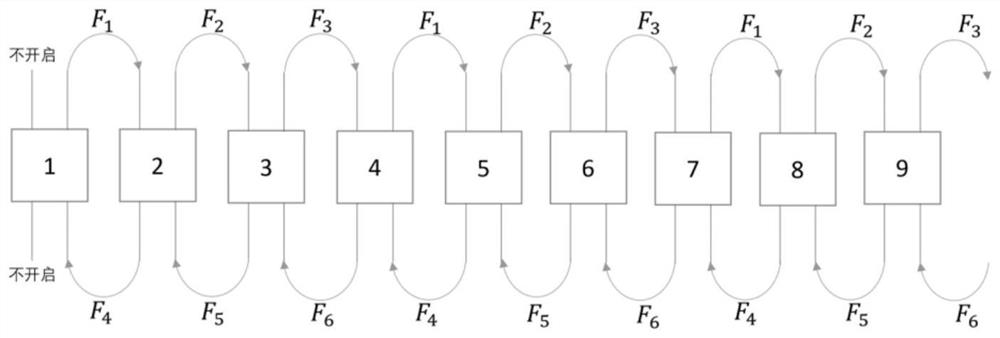
The present invention relates to a wireless communication networking method with a long single-chain structure used in an underground roadway environment, belonging to the field of wireless communication applications. S1: Deploy relay node equipment on-site in the roadway environment, and use a long single-chain topology to form a wireless network ;S2: Set the sequence number for each relay node device, and control the sequence number to increase sequentially along the chain from the starting point; S3: The relay node device automatically calculates and selects the appropriate frequency according to its own sequence number, and automatically turns on the appropriate frequency antenna. By configuring the networking method of sequential conditions, in the long single-chain network, two frequencies are used for sending and receiving between two hops formed by consecutive nodes, and different frequencies are used for transmission between each hop, which avoids bandwidth hopping caused by time-division duplexing The number keeps halving. Between any two nodes, only the corresponding frequency antennas are turned on according to the rules, and there is only data exchange overhead in the single-node device, which reduces the occupied bandwidth and increased delay caused by these computing overheads.

Description

technical field [0001] The invention belongs to the field of wireless communication applications, and relates to a wireless communication networking method with a long single-chain structure used in an underground tunnel environment. Background technique [0002] In narrow, long, narrow and closed spaces, such as underground tunnels, ad hoc wireless communication devices are used to form a network, especially when node routers are deployed in tunnels to form a long single-chain network, and the entire network presents a polyline shape. [0003] There are two important indicators of wireless communication in this environment, one is the wireless transmission distance between two nodes, and the other is the network capacity maintained after relaying multiple hops. [0004] In the roadway environment, wireless communication technology generally uses electromagnetic waves as a means of wireless communication. The roadway environment is a restricted space, and the propagation of...

Claims


Application Information

Patent Timeline
Patent Type & Authority Patents(China)
IPC IPC(8): H04W40/22
CPCH04W40/22Y02D30/70
Inventor 李昀杨俊燕雷毅谈薛春荣
Owner 重庆科华安全设备有限责任公司
Learn More