
Rail fixing system

A technology for fixing systems and rails, applied in the directions of rails, fixed rails, railway fixtures, etc., which can solve the problems of component tolerances, difficult lateral force distribution to multiple installed fixed elements, etc.

Active Publication Date: 2020-12-01
SCHWIHAG
View PDF8 Cites 0 Cited by
  • Summary
  • Abstract
  • Description
  • Claims
  • Application Information

AI Technical Summary

Problems solved by technology

Furthermore, due to component and manufacturing tolerances, especially of the concrete body, it is difficult in the prior art to distribute the transverse forces evenly over the multiple mounted fixing elements

Method used


Image

  • Rail fixing system
  • Rail fixing system

Examples


Embodiment Construction

[0034] Preferred exemplary embodiments are described below with reference to the drawings. In this case, identical, similar or identically acting elements are provided with the same reference symbols in the figures, and a repeated description of these elements is partially omitted in order to avoid redundancy.

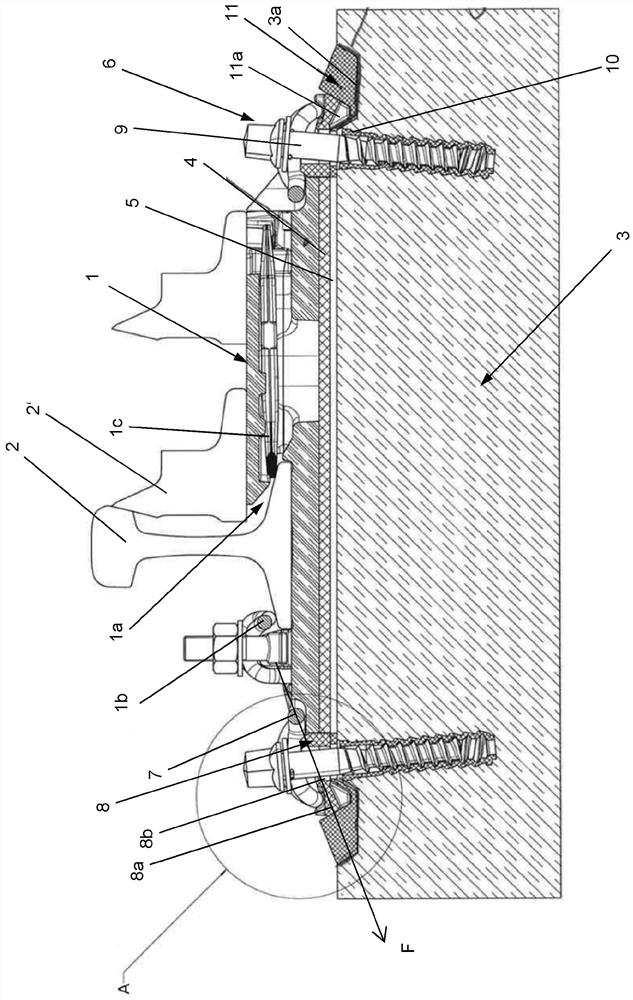
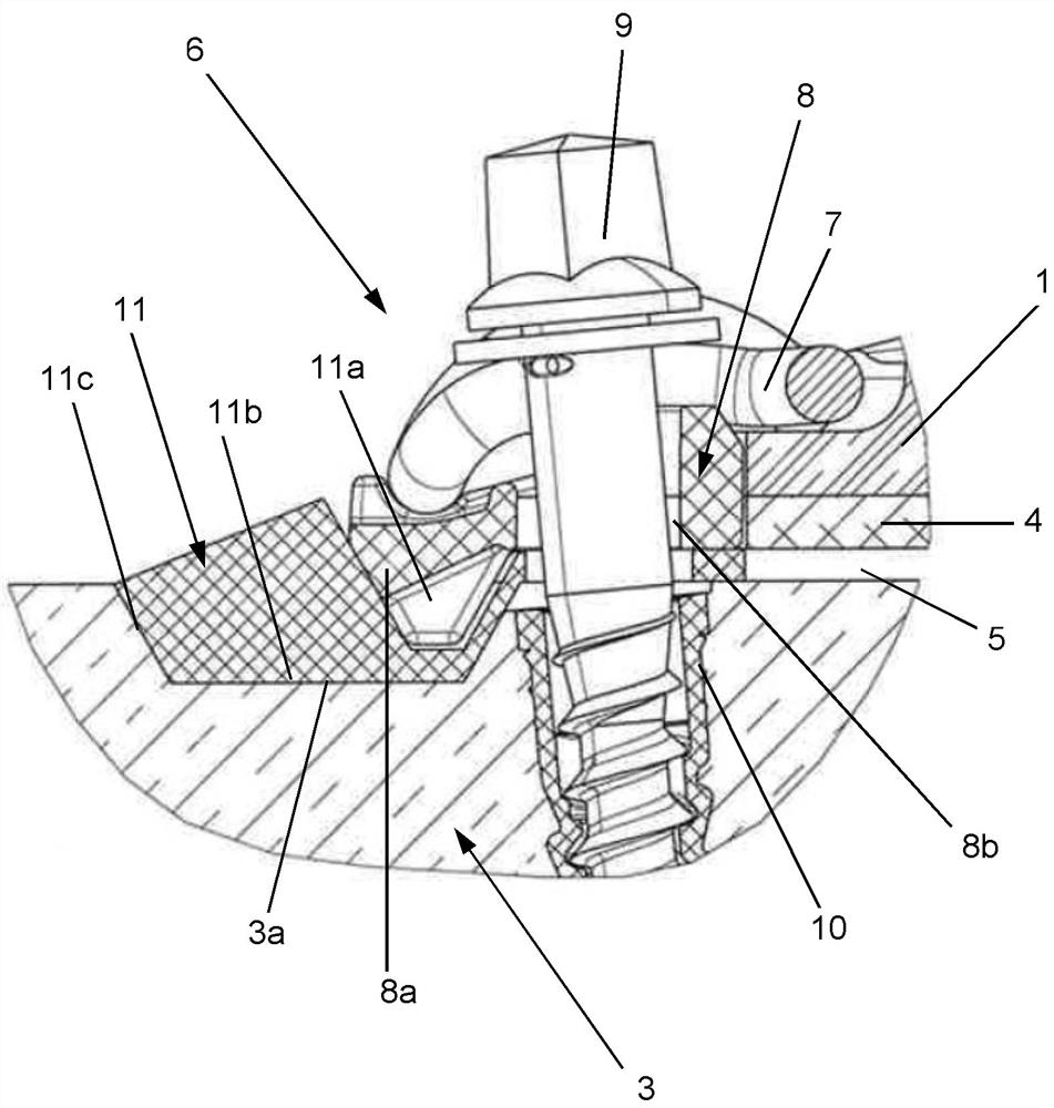
[0035] track fixing system (in figure 1 with 2 ) has a track pad 1 (also referred to as a "slider bed") for holding a rail 2 resting on the track pad. The rail backing plate 1 is, for example, a shaped part made of steel and is used together with other components of the rail fastening system to securely anchor the rail 2 to a foundation 3 , which is preferably a fixed foundation made of concrete.

[0036] In the present embodiment, the track 2 is located in the region of the switch. For this reason, in figure 1 In , an additional track section 2' is shown at two positions. The track section 2' rests on the corresponding section of the track backing plate 1 and can...


PUM


Abstract

The invention relates to a rail fastening system for securing rail at lower track structure. The rail fastening system for fastening rail (2) on lower track structure (3), preferably on ballast-less track, includes at least one fixing element (6) for mounting rail (2) on lower track structure (3). At that, fixing element (6) has angular guide plate (8), which is adapted so that in mounted state toremove transverse forces from rail (2) in track lower structure (3), and thrust element (11), which is adapted to fit tightly butt-end to angular guide plate (8) and to be geometrically closed in recess (3a) of lower structure (3) of track.

Description

technical field [0001] The invention relates to a rail fastening system for fastening a rail to a foundation, preferably a fixed road foundation. The rail fastening system has an angled guide plate, which is provided for dissipating transverse forces from the rail into the foundation. Background technique [0002] It is known that railway tracks are fastened to concrete sleepers in the use of so-called "horn guides". The angular deflectors help to transmit the wheel transverse forces into the concrete by means of a form-fitting connection with corresponding recesses (also referred to as “grooves”). Thus, DE 101 39 198 A1 describes such a fastening for rail elements. The angled guide plates, referred to here as “coupling units”, each bear against the base plate with their stop surfaces. At the same time, the angled guide plates engage into corresponding recesses of the concrete sleeper. [0003] For high-speed road sections, road sections with increased requirements for n...

Claims


Application Information

Patent Timeline
Patent Type & Authority Applications(China)
IPC IPC(8): E01B9/38E01B9/44E01B9/46
CPCE01B7/22E01B9/30E01B9/38E01B9/44E01B9/46E01B9/48E01B9/483E01B9/68E01B2201/04E01B2204/06E01B2204/09
Inventor S.林哈德F.迈耶
Owner SCHWIHAG
Learn More