
Comprehensive energy monitoring system and method based on multi-energy cooperation

A comprehensive energy and monitoring system technology, applied in resources, data processing applications, instruments, etc., can solve the problems that the control strategy cannot be calculated and changed, cannot be changed in real time, generates control strategies, and the interval is short, so as to improve the generation efficiency and accuracy, realize intelligence and self-adaptation, and improve the effect of achievement rate

Pending Publication Date: 2020-11-20
SHANDONG LUNENG SOFTWARE TECH
View PDF0 Cites 4 Cited by
  • Summary
  • Abstract
  • Description
  • Claims
  • Application Information

AI Technical Summary

Problems solved by technology

[0005] In the above implementation scheme, when the manual remote control requires multi-functional cooperation and requires multiple operations to be performed simultaneously or sequentially in a short period of time, due to problems such as many operations, short intervals, and complicated sequences, manual remote control is incompetent and can only be performed by the system. Strategies are formulated and executed automatically by the program
[0006] At present, the strategy of multi-energy collaboration is mostly to formulate the execution strategy for the next day in advance according to the energy use plan. This model has three major drawbacks. First, it needs to manually modify the energy use plan every day, which is large and frequent; second, it can only The next day’s execution strategy is formed according to the plan, which lacks flexibility and cannot be changed in real time to generate a control strategy; third, the execution of the control strategy cannot be calculated and changed in real time according to the actual execution situation

Method used

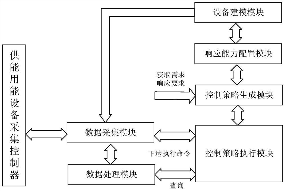
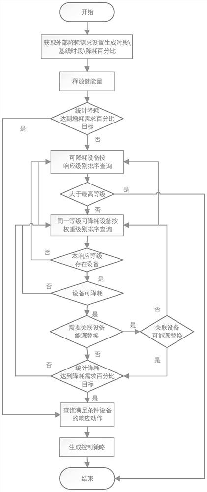

Image

  • Comprehensive energy monitoring system and method based on multi-energy cooperation
  • Comprehensive energy monitoring system and method based on multi-energy cooperation
  • Comprehensive energy monitoring system and method based on multi-energy cooperation

Examples


Embodiment 1

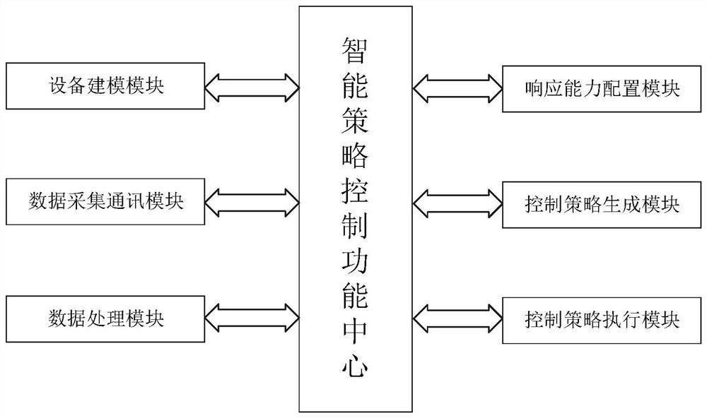
[0059] See attached figure 1 As shown, this embodiment discloses a comprehensive energy monitoring system based on multi-energy cooperation, including an intelligent strategy control function center, which is connected with the equipment modeling module, data acquisition and communication module, data processing module, and response capability configuration module respectively. , a control strategy generation module, and a control strategy execution module.

[0060] The intelligent strategy control function center includes a server, wherein the server is respectively connected with the data acquisition communication module and the data processing module. Wherein, the equipment modeling module, the response capability configuration module, the control strategy generation module, and the control strategy execution module are configured in the server.

[0061] In a specific implementation example, the equipment modeling module is mainly used to establish an enterprise energy inf...


PUM


Abstract

The invention discloses a comprehensive energy monitoring system and method based on multi-energy cooperation, and the system comprises a server which communicates with a processor, and the processorreceives the energy consumption data, collected in real time, of various types of energy consumption equipment, carries out the consumption statistics and charging statistics of the real-time data ofall types of energy consumption equipment, and carries out the minute-level storage; the server generates a control strategy in real time for consumption reduction and consumption increase in different time periods based on the data stored in the processor and the response capability configuration data of the energy consumption equipment and the energy supply equipment; and the server analyzes therunning states of the equipment and the associated equipment in real time, performs serialized operation control on the associated equipment according to a control strategy, and controls the switching and consumption of various energy consumption equipment, thereby achieving the purpose of consumption reduction or increase.

Description

technical field [0001] The disclosure belongs to the technical field of integrated energy monitoring and management, and in particular relates to an integrated energy monitoring system and method based on multi-energy cooperation. Background technique [0002] The statements in this section merely provide background information related to the present disclosure and do not necessarily constitute prior art. [0003] With the acceleration of national energy conservation and emission reduction and the rapid development of various new energy power generation and energy storage technologies, multi-energy collaboration and multi-energy complementary applications are becoming more and more widely used, and higher requirements are placed on comprehensive energy consumption monitoring and management. [0004] Conventional energy monitoring systems pay more attention to the collection and monitoring of production energy-consuming equipment, as well as the statistics of various data. T...

Claims


Application Information

Patent Timeline
Patent Type & Authority Applications(China)
IPC IPC(8): G06Q50/06G06Q10/06
CPCG06Q50/06G06Q10/06315Y02P90/82
Inventor 董俊杰姚燕冰徐金晔严娜何志超张宗慧杨勇刘雷段连君胡勇
Owner SHANDONG LUNENG SOFTWARE TECH
Learn More