A Vibration Damping Device with Strong Intervention

A vibration damping device and powerful technology, applied in the direction of shock absorbers, liquid shock absorbers, shock absorbers, etc., can solve the problems of high cost, low reliability, low safety, complex monitoring and control systems, etc. The effect of reducing the degree, which is conducive to the later modification, and increasing the heat dissipation area

Inactive Publication Date: 2022-04-01
日照普拉沃夫机械制造有限公司
View PDF13 Cites 0 Cited by
  • Summary
  • Abstract
  • Description
  • Claims
  • Application Information

AI Technical Summary

Problems solved by technology

[0003] In the prior art, the damping size is adjusted by passively controlling the hydraulic pressure of the hydraulic cylinder used for guidance and resistance, thereby changing the vibration damping mode of the vehicle, but this method either cannot actively make adaptive adjustments according to road conditions, or requires complicated monitoring and control system with complex structure and high cost
[0004] Existing shock absorbers still have heat dissipation problems that affect the actual resistance effect and the service life of the damping cylinder, such as the high temperature of the damping cylinder
[0005] Due to the harsh environment of the suspension system of the vehicle, the low ground clearance, and frequent physical damage caused by wading and mudstones, the reliability and safety of installing and installing electronic devices on various parts of the suspension are low. It is conducive to the layout of components, which is one of the reasons why the suspension system is difficult to achieve intelligent control

Method used


Image

  • A Vibration Damping Device with Strong Intervention
  • A Vibration Damping Device with Strong Intervention
  • A Vibration Damping Device with Strong Intervention

Examples


Embodiment Construction

[0036] The following are specific embodiments of the present invention and in conjunction with the accompanying drawings, the technical solutions of the present invention are further described, but the present invention is not limited to these embodiments.

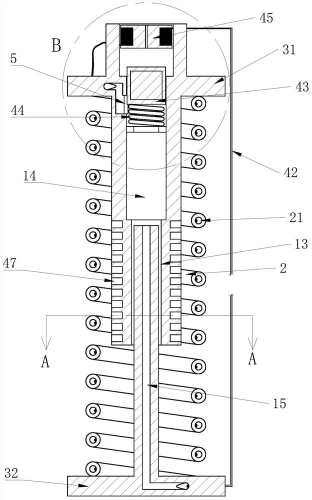
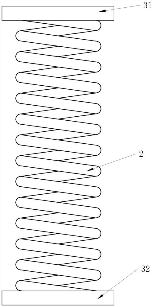
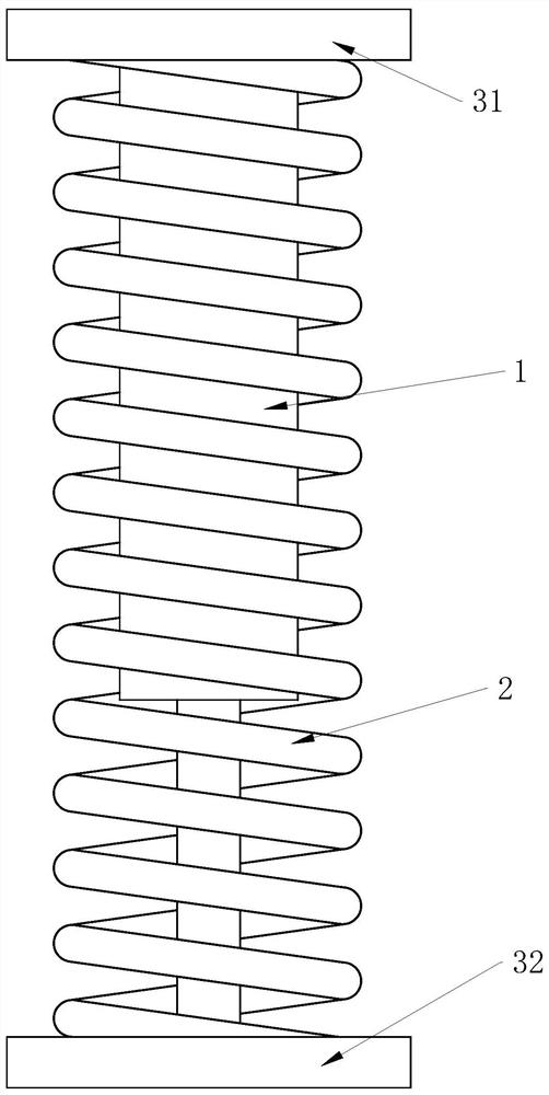
[0037] Such as figure 1 , figure 2 , image 3 , Figure 4 , Figure 5 and Figure 6 As shown, it includes a vehicle frame, four wheels and a shock absorber connected between the vehicle frame and each wheel. The shock absorber includes a damping cylinder 1, a damping spring 2 sleeved outside the damping cylinder 1, and a shock absorber connected to the damping cylinder 1. The upper mount 31 on the upper end of the vibrating spring 2 is connected to the lower mount 32 on the lower end of the damping spring 2, the upper mount 31 is connected to the vehicle frame, and the lower mount is connected to the wheel;

[0038] The damping cylinder 1 includes a cylinder body 11 and a guide rod 12. The upper end of the cylinder b...


PUM


Abstract

The invention provides a strong intervention damping device, which belongs to the technical field of automobiles. It includes a damping cylinder and a damping spring sleeved outside the damping cylinder. The damping spring is a hollow spring with a damping hole inside. A number of first wires are passed through the damping hole, and each first wire is connected in parallel to a second wire. The upper end of the liquid chamber is slidingly connected with a pressure regulating piston, and the upper mounting seat is fixed with an armature block above the pressure regulating piston. The second wire is wound on the armature block in the same direction. The magnetic pole direction of the electromagnetic structure formed after the second wire is energized is the first permanent magnet strip on the same straight line; the permanent magnet group includes a number of second permanent magnet strips that are evenly distributed in the circumferential direction outside the cylinder axis; the damping hole and the liquid storage The cavities are connected through a liquid outlet channel, and the damping spring is in the initial state, and the pressure regulating piston partially blocks the liquid outlet channel. The invention has the advantages of being able to self-adaptively adjust the rigidity of the damping device with high strength.

Description

technical field [0001] The invention belongs to the technical field of automobiles, and relates to a strong intervention damping device. Background technique [0002] The damping effect of the suspension / shock absorber of automobiles (including other vehicles) is generally formatted, that is to say, the damping effect after manufacture and installation cannot be actively adjusted, but in fact, for different driving Road conditions, the requirements for the damping effect in the ideal state are different. For example, when passing a raised obstacle on the ground such as a speed bump, the most ideal state is: at the initial stage of contacting the obstacle, the wheels are quickly approached relative to the body to compensate for the raised surface on the ground. The longitudinal elevation of the vehicle body caused by the sudden upward movement of the wheels, after crossing the highest point of the raised obstacle, it is hoped that the wheels will move away from the vehicle bo...

Claims


Application Information

Patent Timeline
Patent Type & Authority Patents(China)
IPC IPC(8): F16F9/16F16F9/504F16F9/516B60G17/0165
CPCF16F9/16F16F9/504F16F9/516B60G17/0165F16F2232/08
Inventor 黄家华
Owner 日照普拉沃夫机械制造有限公司
Why Eureka
Try Eureka