Coaxial electric tool
A power tool, coaxial technology, applied in the field of tools, can solve the problems of inability to ensure the axis of the rotor and the cylinder, affecting the normal use of the power tool, wasting work time, etc., to save work time, not easy to lose, and avoid trivial parts Effect
- Summary
- Abstract
- Description
- Claims
- Application Information
AI Technical Summary
Problems solved by technology
Method used
Image

Examples
Embodiment 1
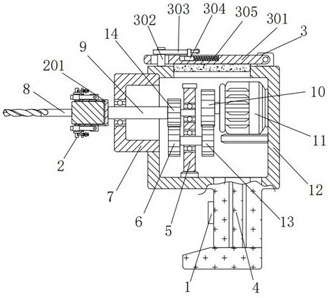
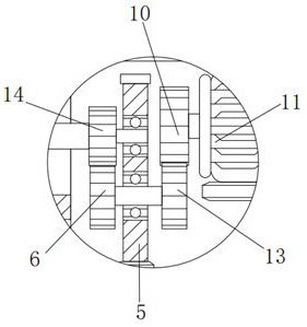
[0030] A coaxial electric tool, including a handle 4, characterized in that a switch 1 is installed on the left side of the handle 4, a box body 12 is connected to the top of the handle 4, and a casing is connected to the upper left side of the box body 12 7. The inner side of the housing 7 is provided with a round rod 9, the left side of the outer wall of the round rod 9 is rotationally connected with the inner wall of the left end of the housing 7 through a bearing, and the bearing makes the round rod 9 rotate on the inner wall of the left end of the housing 7 when it is stressed. The right side of round rod 9 is provided with first gear 14, and the left end of first gear 14 is fixedly connected with the right end of round rod 9, and the bottom of first gear 14 is provided with second gear 6, and the top left side of second gear 6 is connected with The bottom of the first gear 14 is meshed and connected, the right side of the second gear 6 is provided with a riser 5, the bott...
Embodiment 2
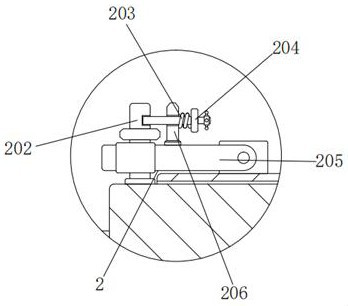
[0032] As an option, see figure 1 , 3, 4 and 5, coaxial electric tools, the left side of the round rod 9 is provided with a fixing device 2, and the fixing device 2 includes a cylinder 201, a short rod 202, a first spring 203, a square rod 204, a long plate 205 and a short block 206, the right end of the cylinder 201 is fixedly connected with the left end of the round rod 9, the inner wall of the cylinder 201 is matched with the right side of the outer wall of the rotating head 8, the outer side of the cylinder 201 is provided with a short rod 202, and the bottom of the upper short rod 202 The bearing is rotatably connected to the top left end of the cylinder 201, and the outer wall of the short rod 202 is in clearance fit with the inner wall of the left channel of the long plate 205. The short rods 202 are axisymmetrically distributed with the rotor 8 as the axis, so that the design can be rotated in opposite directions. When the head 8 is fixed, ensure that the rotating hea...
Embodiment 3
[0035] As an option, see figure 1 and 6 , a coaxial electric tool, a rotating device 3 is provided above the box body 12, and the rotating device 3 includes a horizontal plate 301, a vertical block 302, a long rod 303, a slider 304 and a second spring 305, and the bottom of the vertical block 302 is in contact with the box The top left end of the body 12 is fixedly connected, the right side of the vertical block 302 is provided with a horizontal plate 301, the bottom of the horizontal plate 301 is fixedly connected with a rubber pad, and the rubber pad acts as a seal. The front end face of the top right side of the box body 12 is rotatably connected, and the pin shaft can rotate at the front end face of the top right side of the box body 12 when the horizontal plate 301 is stressed. The outer wall clearance fit of 302, the right side of vertical block 302 is provided with long bar 303, and the left side of outer wall of long bar 303 is matched with the inner wall clearance of...
PUM
 Abstract
Description
Claims
Application Information
 - R&D
- Intellectual Property
- Life Sciences
- Materials
- Tech Scout
- Unparalleled Data Quality
- Higher Quality Content
- 60% Fewer Hallucinations
Browse by: Latest US Patents, China's latest patents, Technical Efficacy Thesaurus, Application Domain, Technology Topic, Popular Technical Reports.
© 2025 PatSnap. All rights reserved.Legal|Privacy policy|Modern Slavery Act Transparency Statement|Sitemap|About US| Contact US: help@patsnap.com