Microphone mounting structure and wireless earphone
A technology of mounting structure and microphone, which is applied in the directions of earpiece/headphone accessories, earphone manufacturing/assembly, sensors, etc., can solve the problems of high cost, many production process steps, complicated assembly, etc., and achieves low production cost, convenient production and assembly steps, simple structure
- Summary
- Abstract
- Description
- Claims
- Application Information
AI Technical Summary
Problems solved by technology
Method used
Image

Examples
Embodiment 1
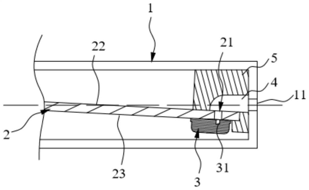
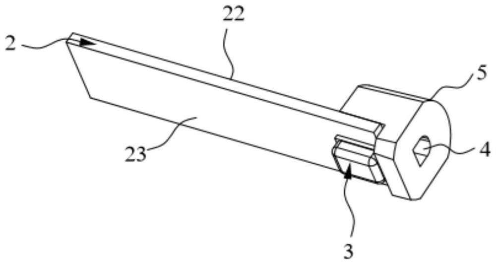
[0035] Such as Figure 1-Figure 3 As shown, the embodiment of the present invention provides a microphone mounting structure, including a handle portion 1, an internal circuit board 2, a microphone 3, and a sound guide 5. The handle 1 is cylindrical and is used by the operator to hold it. It has a first cavity with a bottom at one end. The bottom is provided with a through microphone hole 11 that communicates with the first cavity. The external sound passes through the microphone. The hole 11 enters the first cavity of the handle 1. The internal circuit board 2 is arranged in the first cavity of the handle 1 and extends along the length of the handle 1. The end of the internal circuit board 2 close to the microphone appearance hole 11 deviates from the axis of the microphone appearance hole 11; both sides of the internal circuit board 2 All are equipped with electronic devices. The microphone 3 is fixed to one end of the lower surface 23 of the internal circuit board 2 by ref...
Embodiment 2
[0039] Such as Figure 4 As shown, the embodiment of the present invention provides a microphone mounting structure, including a handle portion 1, an internal circuit board 2, a microphone 3, and a sound guide 5. The structure of the handle 1 is the same as that of the first embodiment, with a first cavity and a microphone appearance hole 11 communicating with the first cavity; the installation method of the internal circuit board 2 is also the same as that of the first embodiment. The difference between this embodiment and the first embodiment lies in: the position of the microphone 3, the structure of the internal circuit board 2, and the structure and installation manner of the sound guide 5 are different.
[0040] In this embodiment, the microphone 3 is fixed to one end of the upper surface 22 of the internal circuit board 2 by reflow soldering, and the sound receiving hole 31 of the microphone 3 is located on the non-welded surface of the microphone 3. Since the sound receiv...
Embodiment 3
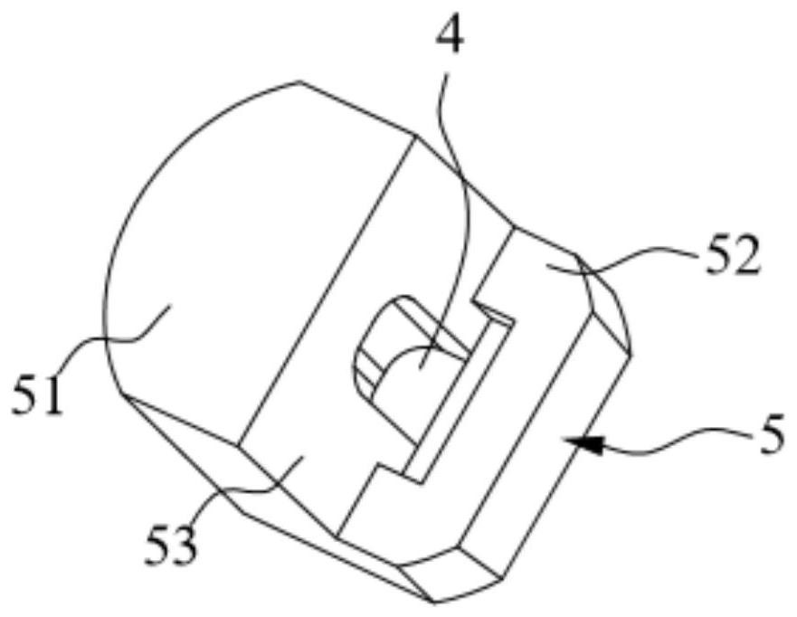
[0044] This embodiment provides a wireless headset, including the microphone installation structure described in any one of the first embodiment and the second embodiment. In other words, the microphone 3 of this embodiment can be fixed on the lower surface 23 of the internal circuit board 2 and located outside the sound guide 5, wherein the sound receiving hole 31 is located on the side of the microphone 3 that contacts the internal circuit board 2 and is connected to the internal circuit The sound guide holes 21 on the board 2 are aligned. At this time, one end of the sound guide channel 4 is connected to the sound guide hole 21, and the other end is connected to the microphone appearance hole 11, so as to realize the sound receiving function of the microphone 3. Alternatively, the microphone 3 of this embodiment may also be located on the upper surface 22 of the internal circuit board 2 and inside the sound guide sleeve 5. The sound receiving hole 31 is located on the non-wel...
PUM
 Abstract
Description
Claims
Application Information
 - Generate Ideas
- Intellectual Property
- Life Sciences
- Materials
- Tech Scout
- Unparalleled Data Quality
- Higher Quality Content
- 60% Fewer Hallucinations
Browse by: Latest US Patents, China's latest patents, Technical Efficacy Thesaurus, Application Domain, Technology Topic, Popular Technical Reports.
© 2025 PatSnap. All rights reserved.Legal|Privacy policy|Modern Slavery Act Transparency Statement|Sitemap|About US| Contact US: help@patsnap.com