Automatic drilling device for rows of holes in printed circuit board

A drilling device and circuit board technology, applied in metal processing and other directions, can solve the problems of uneven hole spacing, hidden safety hazards, low drilling efficiency, etc., and achieve the effect of uniform and stable hole spacing, good efficiency, and avoidance of accidental damage.

Inactive Publication Date: 2020-11-03
宁波变雪电子科技有限公司
View PDF0 Cites 0 Cited by
  • Summary
  • Abstract
  • Description
  • Claims
  • Application Information

AI Technical Summary

Problems solved by technology

[0002] The circuit board can be called a printed circuit board or a printed circuit board. The circuit board makes the circuit miniaturized and intuitive, and plays an important role in mass production of fixed circuits and optimizing the layout of electrical appliances; there are often many small holes on the circuit board, and some may be Rows of shapes, these small holes play a very important role for the circuit board. At present, the drilling operation of the circuit board may still need to be done manually, and there are obviously some shortcomings in manual drilling, such as low drilling efficiency, For the row of holes, there may be uneven hole spacing. At the same time, the circuit board is relatively precise. Manual drilling may cause damage to the circuit board. At the same time, manual drilling also has potential safety hazards. Device for automatic drilling and arranging holes on the board

Method used


Image

  • Automatic drilling device for rows of holes in printed circuit board
  • Automatic drilling device for rows of holes in printed circuit board
  • Automatic drilling device for rows of holes in printed circuit board

Examples


Embodiment Construction

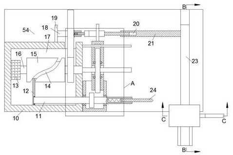
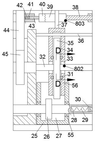
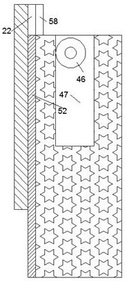
[0015] Combine below Figure 1-5 The present invention is described in detail, and for convenience of description, the orientations mentioned below are now stipulated as follows: figure 1 The up, down, left, right, front and back directions of the projection relationship itself are the same.

[0016] refer to Figure 1-5 According to an embodiment of the present invention, an automatic drilling device for arranging holes on a circuit board includes a bottom plate 54, a power box 10 is fixedly connected to the front surface of the bottom plate 54, and a power chamber is provided inside the power box 10 17. The left wall of the power chamber 17 is fixedly connected with a motor 13, the right end of the motor 13 is connected with a motor shaft 16 whose right end is rotatably connected to the right wall of the power chamber 17, and the motor shaft 16 is fixed Connected with a rotating cylinder 15, the outer surface of the rotating cylinder 15 is provided with a groove 14, and th...


PUM


Abstract

The invention discloses an automatic drilling device for rows of holes in a printed circuit board. The automatic drilling device comprises a bottom plate, wherein a power box is fixedly connected to the front surface of the bottom plate, a power cavity is formed inside the power box, and a motor is fixedly connected to the left wall of the power cavity; and the right end of the motor is in power connection with a motor shaft with the right end rotationally connected to the right wall of the power cavity, a rotating cylinder is fixedly connected to the motor shaft, and a groove is formed in theouter surface of the rotating cylinder. The drilling effect of the row of holes in the printed circuit board can be achieved in a full-automatic mode, due to the fact that a clamping plate moves forthe same time each time and the rotating speed of the motor shaft is not changed, the distance between the holes can be uniform and stable; and meanwhile, the printed circuit board is a precise object, and the printed circuit board can be better protected through full-automatic drilling, so that accidental damage can be avoided, safety is higher, the drilling efficiency is better, and the automatic drilling device is worthy of popularization.

Description

technical field [0001] The invention relates to the related technical field of circuit boards, in particular to an automatic drilling device for arranging holes on a circuit board. Background technique [0002] The circuit board can be called a printed circuit board or a printed circuit board. The circuit board makes the circuit miniaturized and intuitive, and plays an important role in mass production of fixed circuits and optimizing the layout of electrical appliances; there are often many small holes on the circuit board, and some may be Rows of shapes, these small holes play a very important role for the circuit board. At present, the drilling operation of the circuit board may still need to be done manually, and there are obviously some shortcomings in manual drilling, such as low drilling efficiency, For the row of holes, there may be uneven hole spacing. At the same time, the circuit board is relatively precise. Manual drilling may cause damage to the circuit board. A...

Claims


Application Information

Patent Timeline
Patent Type & Authority Applications(China)
IPC IPC(8): B26F1/16B26D5/08B26D5/06B26D7/02B26D7/06
CPCB26D5/06B26D5/083B26D5/086B26D7/025B26D7/06B26F1/16B26F2210/08
Inventor 王俊宇
Owner 宁波变雪电子科技有限公司
Why Eureka
Try Eureka