Agricultural rice cutting-off equipment

A technology for cutting equipment and rice, applied in the field of agricultural rice cutting equipment, can solve the problems of hand fatigue, cumbersome operation, heavy cutting parts, etc., and achieve the effect of convenient operation

Active Publication Date: 2020-11-03
浏阳市湘绿源农业发展有限公司
View PDF5 Cites 0 Cited by
  • Summary
  • Abstract
  • Description
  • Claims
  • Application Information

AI Technical Summary

Problems solved by technology

[0005] In order to overcome the disadvantages that two people need to work together to cut the rice, the operation is cumbersome, hand fatigue is likely to be caused by continuing to hold the rice manually, and the cutting parts are heavy, and the use is time-consuming and labor-intensive. The technical problem of the present invention is to provide an easy-to-operate, Automatic cutting agricultural rice cutting equipment

Method used


Image

  • Agricultural rice cutting-off equipment
  • Agricultural rice cutting-off equipment
  • Agricultural rice cutting-off equipment

Examples


Embodiment 1

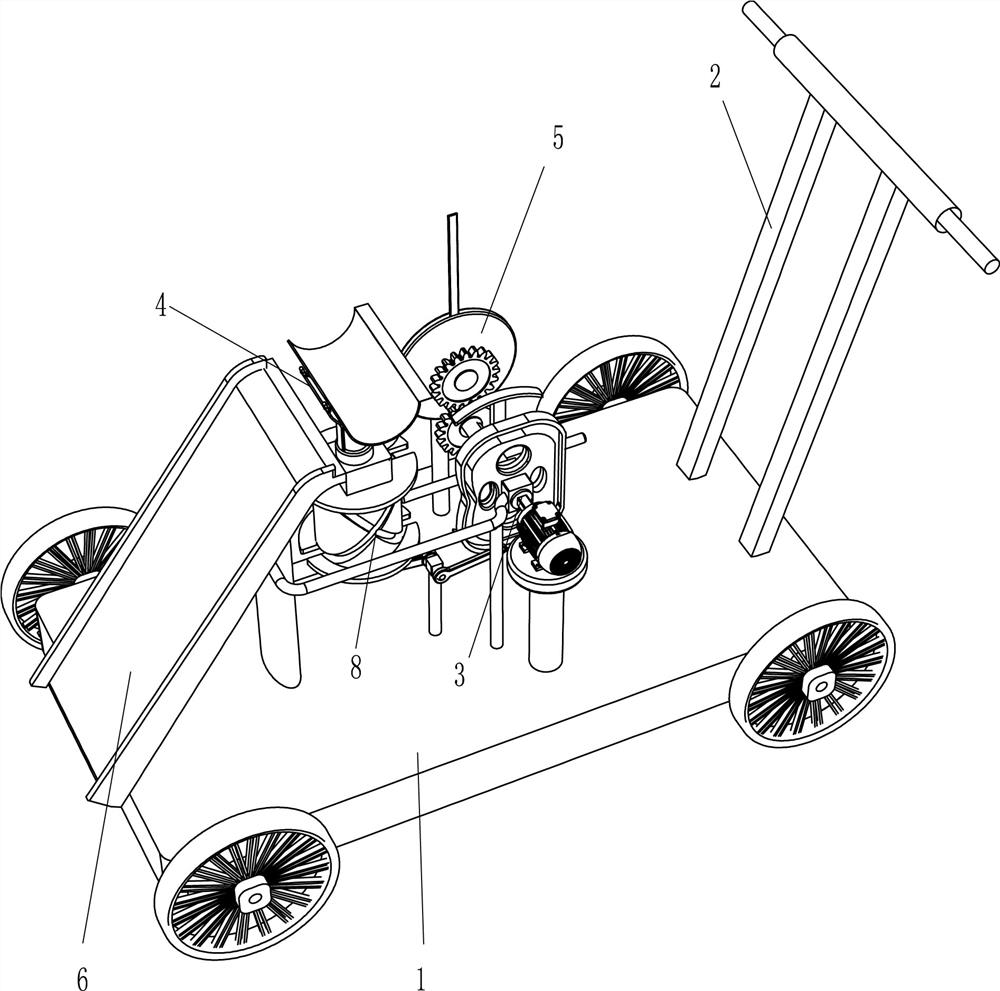
[0022] Such as Figure 1-4 As shown, an agricultural rice cutting device includes a vehicle frame 1, a push handle 2, a lifting mechanism 3, an arc-shaped placement plate 4, a cutting mechanism 5, and a slide plate 6. The right side of the top of the vehicle frame 1 is provided with a push handle 2, and the vehicle frame 1 The top center is provided with a lifting mechanism 3, and the top of the lifting mechanism 3 is provided with an arc-shaped placement plate 4. The rear left part of the top of the frame 1 is provided with a cutting mechanism 5, which is connected to the lifting mechanism 3 by transmission. The top left of the frame 1 Side is provided with slide plate 6, and slide plate 6 places plate 4 near arc.

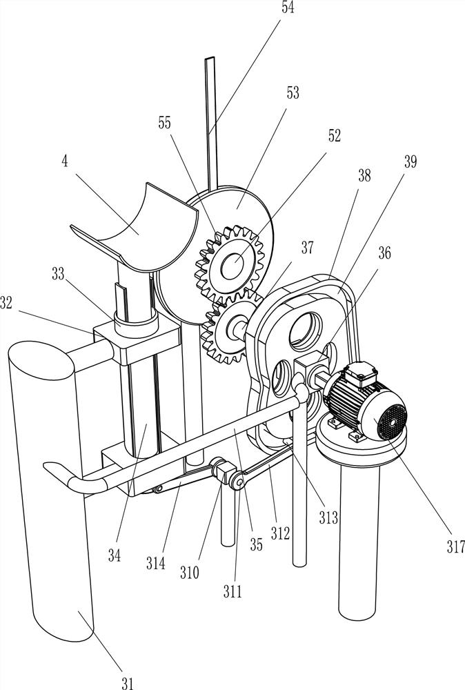
[0023] The lifting mechanism 3 includes a mounting column 31, a first bearing seat 32, a sliding sleeve 33, a lifting rod 34, a connecting rod 35, a second bearing seat 36, a rotating shaft 37, a cam 38, a third bearing seat 310, and a first rotating shaft 311 , ...

Embodiment 2

[0027] On the basis of Example 1, such as Figure 1-4 As shown, it also includes a rotating cylinder 7, a fixed sleeve 10, a special-shaped rod 11, an arc-shaped guide plate 12 and a guide post 13. The rotating cylinder 7 is installed on the lifting rod 34, and the rotating cylinder 7 can slide along the axial direction of the lifting rod 34. The rotating cylinder 7 is located between the two first bearing seats 32, and the side wall of the rotating cylinder 7 is crossed with an arc-shaped groove 8, and the upper and lower discs of the rotating cylinder 7 are located at the exit positions of the two ends of the arc-shaped groove 8, and a word groove 9 is formed. The straight groove 9 communicates with the arc groove 8, and the middle part of the rotating shaft 37 is provided with a fixed cover 10, and the side of the fixed cover 10 is symmetrically provided with a special-shaped rod 11 by welding, and the two special-shaped rods 11 are arranged at 180°, and the special-shaped r...


PUM


Abstract

The invention relates to cutting-off equipment, in particular to agricultural rice cutting-off equipment. In order to solve the technical problem, the invention provides the agricultural rice cutting-off equipment which is convenient to operate and capable of automatically cutting. According to the technical scheme, the agricultural rice cutting-off equipment comprises a frame, a lifting mechanism, an arc-shaped placing plate, a cutting mechanism and a sliding plate, wherein pushing handles are arranged at the edge of one side of the top of the frame; the lifting mechanism is arranged in the center of the top of the frame; the arc-shaped placing plate is arranged at the top of the lifting mechanism; the cutting mechanism is arranged on one side close to the lifting mechanism, of the frame,and is in transmission connection with the lifting mechanism; and the sliding plate is arranged on one side away from the pushing handles, of the top of the frame and is close to the arc-shaped placing plate. The effects of convenient operation and automatic cutting are achieved.

Description

technical field [0001] The invention relates to a cutting device, in particular to an agricultural paddy cutting device. Background technique [0002] When the rice is harvested, in order to dry and stack a large amount of rice in an effective space, workers generally use tools to cut off one end of the rice, and the end of the rice that the worker uses to pinch off the rice is just the side that contains more rice. The cut rice will fall to the ground, and then the workers will evenly spread the rice on the ground to dry. [0003] People hold a lot of rice with both hands, and then place the part that needs to be cut under the cutting part, and then another person can pinch off one end of the rice by swinging the cutting part. It is cumbersome to operate with the cooperation of human beings. Continuously holding the rice manually will easily cause hand fatigue, and the cutting parts are heavy, which is time-consuming and labor-intensive to use. [0004] Therefore need a k...

Claims


Application Information

Patent Timeline
IPC IPC(8): A01D45/04A01D69/02A01D69/06A01D57/26
CPCA01D45/04A01D69/02A01D69/06A01D57/26Y02P60/14
Inventor 黄镇明
Owner 浏阳市湘绿源农业发展有限公司
Why Eureka
Try Eureka