Obstacle clearing device

An obstacle removal device and obstacle removal technology, which is applied in the direction of switchgear, roads, electrical components, etc., can solve the problems of large size, inapplicability, time-consuming and labor-intensive obstacle removal equipment, etc.

Active Publication Date: 2020-10-23
GUANGDONG POWER GRID CO LTD +1
View PDF6 Cites 2 Cited by
  • Summary
  • Abstract
  • Description
  • Claims
  • Application Information

AI Technical Summary

Problems solved by technology

Among them, the wrecker crane and the wrecking forklift are suitable for cleaning and removing large items and equipment one by one. This type of wrecking equipment is large in size, complex in structure and high in design cost, and is not suitable for some indoor or space-limited places. Wrecker work, while the wrecker pole is only suitable for the removal of some small objects
However, some large and heavy debris are usually piled up around the power distribution equipment, such as barrels and other roadblocks. The roadblocks block the road around the power distribution equipment, making it impossible for workers to quickly approach the power distribution equipment.
If the obstacles near the power distribution equipment are not cleared in time, it will affect the passage of maintenance personnel in the event of an emergency, which will affect the maintenance efficiency. If these obstacles are manually moved, it will be time-consuming and labor-intensive, and the efficiency will be low

Method used


Image

  • Obstacle clearing device
  • Obstacle clearing device

Examples


Embodiment Construction

[0033] In order to make the technical problems solved by the present invention, the technical solutions adopted and the technical effects achieved clearer, the technical solutions of the present invention will be further described below in conjunction with the accompanying drawings and through specific implementation methods.

[0034] In the description of the present invention, unless otherwise clearly specified and limited, the terms "connected", "connected" and "fixed" should be understood in a broad sense, for example, it can be a fixed connection, a detachable connection, or an integrated ; It can be a mechanical connection or an electrical connection; it can be a direct connection or an indirect connection through an intermediary, and it can be the internal communication of two components or the interaction relationship between two components. Those of ordinary skill in the art can understand the specific meanings of the above terms in the present invention in specific si...


PUM


Abstract

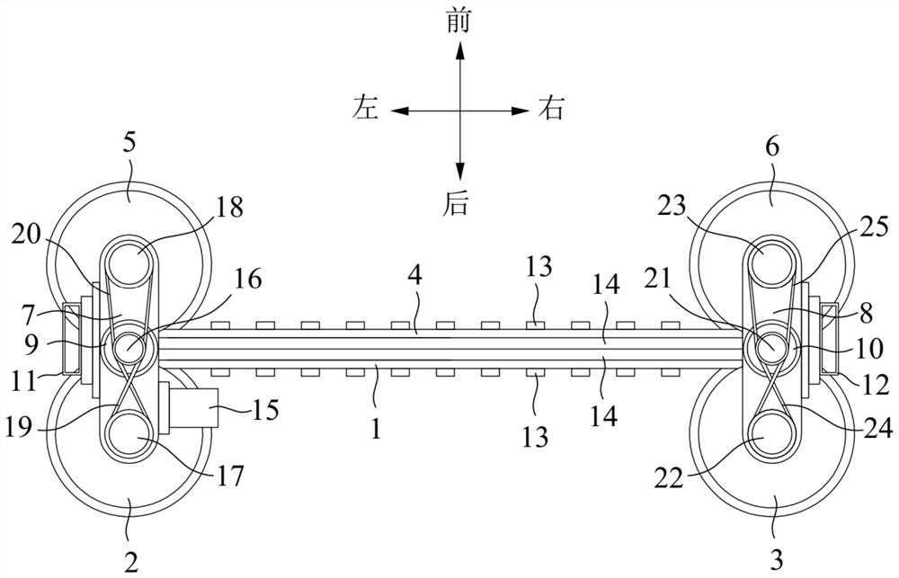
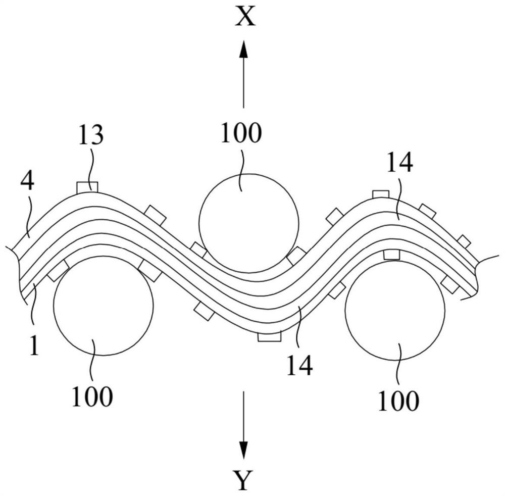
The invention relates to the field of obstacle clearing equipment, and discloses an obstacle clearing device which comprises a first obstacle clearing belt and a second obstacle clearing belt. A firstreel for winding the first obstacle clearing belt is arranged at one end of the first obstacle clearing belt, and a second reel for winding the first obstacle clearing belt is arranged at the other end of the first obstacle clearing belt; a third reel used for winding the second obstacle clearing belt is arranged at one end of the second obstacle clearing belt, a fourth reel used for winding thesecond obstacle clearing belt is arranged at the other end of the second obstacle clearing belt, and the second obstacle clearing belt and the first obstacle clearing belt are arranged side by side atintervals when unfolded. In the case of roadblock clearing, roadblocks around the power distribution cabinet are distributed on the side, back to the second obstacle clearing belt, of the bent firstobstacle clearing belt and the side, back to the first obstacle clearing belt, of the bent second obstacle clearing belt respectively. When the second obstacle clearing belt and the first obstacle clearing belt are wound, the second obstacle clearing belt and the first obstacle clearing belt can push the roadblock to be cleared through tensioning force generated by winding, operation is easy and convenient, the structure is simple, and the design cost is low.

Description

technical field [0001] The invention relates to the technical field of obstacle removal equipment, in particular to an obstacle removal device. Background technique [0002] Electrical Equipment (Electrical Equipment) is a general term for high-voltage distribution cabinets, generators, transformers, power lines, circuit breakers, low-voltage switchgear, switchboards, switch boxes, and control boxes in the power system. Ensuring the cleanliness around the power distribution equipment can effectively ensure that the staff can quickly repair the power distribution equipment. [0003] The obstacle removal device is often used to remove various roadblocks. Currently, the commonly used obstacle removal equipment mainly includes obstacle removal cranes, obstacle removal forklifts, and obstacle removal poles. Among them, the wrecker crane and the wrecking forklift are suitable for cleaning and removing large items and equipment one by one. This type of wrecking equipment is large ...

Claims


Application Information

Patent Timeline
IPC IPC(8): E01F9/70H02B3/00
CPCE01F9/70H02B3/00
Inventor 沈瑞锡李国良陈文其黄日光曹贵阳谭世钊吴贻标
Owner GUANGDONG POWER GRID CO LTD
Why Eureka
Try Eureka