Side-entry energy storage battery arrangement structure
A technology for arranging structures and energy storage batteries, which is applied to batteries, structural parts, electric power devices, etc., and can solve problems such as difficult disassembly and low assembly efficiency
- Summary
- Abstract
- Description
- Claims
- Application Information
AI Technical Summary
Problems solved by technology
Method used
Image
Examples
Embodiment 1
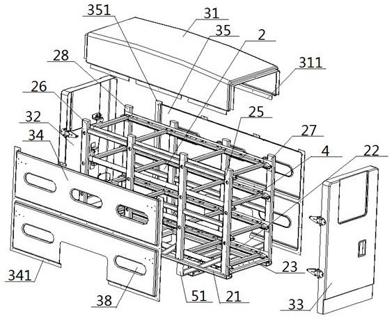
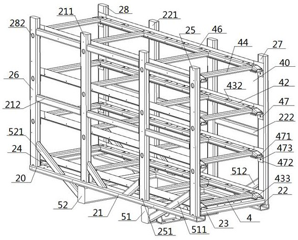
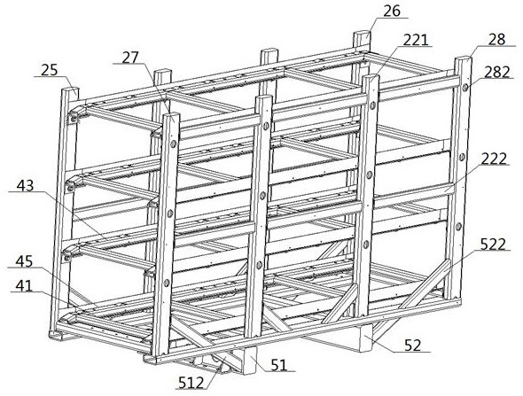
[0063] see figure 1 — Figure 8 , a side-entry energy storage battery arrangement structure, including a battery frame body 2 and a protective device 3 sheathed outside; the battery frame body 2 includes a front beam 21, a rear beam 22, a left longitudinal beam 23 and a right longitudinal beam 24. The left and right ends of the front beam 21 are vertically connected with the bottom ends of the front left vertical beam 25 and the front right vertical beam 26 respectively, and the left and right ends of the rear beam 22 are connected with the rear left vertical beam 27 and the rear right vertical beam respectively. The bottom end of the beam 28 is vertically connected, and the position at the intersection of the front cross beam 21 and the front left vertical beam 25 on the front cross beam 21 is connected with the front end of the left longitudinal beam 23. 27 junction is connected with the rear end of the left longitudinal beam 23, the front crossbeam 21 is connected with the...
Embodiment 2
[0066] Basic content is the same as embodiment 1, the difference is:
[0067] The bottom surface of the front beam 21 is located between its left and right ends and is connected to the top surface of the front ends of the left fixed beam 51 and the right fixed beam 52, and the bottom surface of the rear beam 22 is located between its left and right ends. The position between the ends is connected with the top surface of the rear end of the left fixed beam 51 and the right fixed beam 52; The high end passes through the front cross beam 21 and is connected with the side of the front left vertical beam 25, the left side of the rear end of the left fixed beam 51 is connected with the low end of the left rear inclined beam 512, and the high end of the left rear inclined beam 512 passes through The rear crossbeam 22 is connected with the side of the rear left vertical beam 27, the right side of the front end of the right fixed beam 52 is connected with the low end of the right front...
Embodiment 3
[0069] Basic content is the same as embodiment 1, the difference is:
[0070] The battery bracket 4 includes a front guide rail beam 41 and a rear guide rail beam 42, the front side of the front guide rail beam 41 is connected to the inner side of the front left vertical beam 25 and the front right vertical beam 26, and the rear side of the front guide rail beam 41 The side part and the front side of the rear guide rail beam 42 are directly arranged, and the rear side of the rear guide rail beam 42 is connected with the inner side of the rear left vertical beam 27 and the rear right vertical beam 28; the front guide rail beam 41, the rear guide rail beam The structure of 42 is consistent, all comprises the groove beam body 43 and the multiple roller mounting grooves 431 that are set at intervals successively on the top surface thereof, is provided with roller 432 in the roller mounting groove 431, and the top of roller 432 is higher than the groove beam body 43 The top surface...
PUM
 Abstract
Description
Claims
Application Information
 - R&D
- Intellectual Property
- Life Sciences
- Materials
- Tech Scout
- Unparalleled Data Quality
- Higher Quality Content
- 60% Fewer Hallucinations
Browse by: Latest US Patents, China's latest patents, Technical Efficacy Thesaurus, Application Domain, Technology Topic, Popular Technical Reports.
© 2025 PatSnap. All rights reserved.Legal|Privacy policy|Modern Slavery Act Transparency Statement|Sitemap|About US| Contact US: help@patsnap.com


