
Spot-welder head and spot-welding device

A machine head and spot welding technology, applied in auxiliary devices, welding equipment, auxiliary welding equipment, etc., can solve the problems of low yield rate and low efficiency of manual spot welding, and achieve the effect of improving spot welding quality

Inactive Publication Date: 2020-10-09
GEER TECH CO LTD
View PDF5 Cites 1 Cited by
  • Summary
  • Abstract
  • Description
  • Claims
  • Application Information

AI Technical Summary

Problems solved by technology

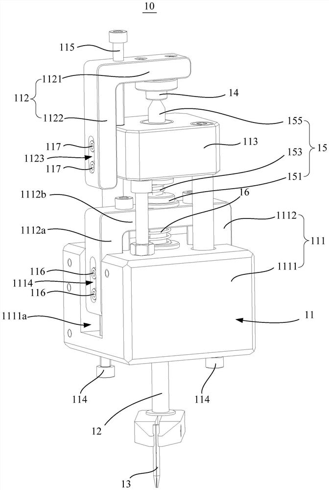
[0003] The main purpose of the present invention is to provide a spot welding head and a spot welding device, aiming to solve the problems of low efficiency and low yield of manual spot welding in the prior art

Method used


Image

  • Spot-welder head and spot-welding device
  • Spot-welder head and spot-welding device
  • Spot-welder head and spot-welding device

Examples


Embodiment Construction

[0050] The following will clearly and completely describe the technical solutions in the embodiments of the present invention with reference to the accompanying drawings in the embodiments of the present invention. Obviously, the described embodiments are only part of the embodiments of the present invention, not all of them. Based on the embodiments of the present invention, all other embodiments obtained by persons of ordinary skill in the art without creative efforts fall within the protection scope of the present invention.

[0051] It should be noted that all directional indications (such as up, down, left, right, front, back...) in the embodiments of the present invention are only used to explain the relationship between the components in a certain posture (as shown in the accompanying drawings). Relative positional relationship, movement conditions, etc., if the specific posture changes, the directional indication will also change accordingly.

[0052]In addition, in th...


PUM


Abstract

The invention discloses a spot-welder head and a spot-welding device applying the spot-welder head. The spot-welder head comprises a pedestal, a slide bar, a spot-welding head, a pressure sensor and atransmission mechanism, wherein the pedestal is provided with a first mounting part and a second mounting part, and the first mounting part is provided with a first mounting hole; the slide bar penetrates the first mounting hole and can move in a reciprocating manner along the axis direction of the first mounting hole; the spot-welding head is connected to the end part of the slide bar and is located below the first mounting part; the pressure sensor is mounted on the second mounting part; the transmission mechanism is located between the first mounting part and the second mounting part, theend part, deviated from the spot-welding head, of the slide bar is connected to the transmission mechanism, the transmission mechanism is stopped by the first mounting part, and the end, deviated fromthe slide bar, of the transmission mechanism is in contact with the pressure sensor, and the transmission mechanism is in elastic contact with the pressure sensor; and the center lines of the slide bar, the pressure sensor and the transmission mechanism are located on a same straight line. According to the technical scheme, the spot-welding efficiency can be improved and the rate of finished products is improved.

Description

technical field [0001] The invention relates to the technical field of spot welding equipment, in particular to a spot welding head and a spot welding device using the spot welding head. Background technique [0002] With the advancement of science and technology, electronic products tend to be intelligent and miniaturized. The corresponding pad area on the circuit board used for welding in electronic products is getting smaller and smaller, and the requirements for spot welding technology are getting higher and higher. The existing manual welding method requires the help of a microscope for welding operations. Not only is the production efficiency low and it is difficult to ensure the welding quality, it is difficult to control the welding pressure on the pads during the manual welding process, which makes the pads easy to fall off after spot welding. Low. Contents of the invention [0003] The main purpose of the present invention is to provide a spot welding head and a...

Claims


Application Information

Patent Timeline
Patent Type & Authority Applications(China)
IPC IPC(8): B23K37/02B23K37/04B23K37/00
CPCB23K37/00B23K37/0247B23K37/0426
Inventor 马凯
Owner GEER TECH CO LTD
Learn More