Rotor blade of wind turbine, having splitter plate

A technology of rotor blades and deflectors, applied in the field of optimizing the rotor blades, can solve problems such as increased noise emission, increased air resistance, and inability to achieve lift, and achieves the effect of easy installation and small transportation size

Active Publication Date: 2020-10-02
WOBBEN PROPERTIES GMBH
View PDF13 Cites 0 Cited by
  • Summary
  • Abstract
  • Description
  • Claims
  • Application Information

AI Technical Summary

Problems solved by technology

However, rotor blades with an at least partially blunt trailing edge have the disadvantage that, due to the smaller blade depth, the lift power is reduced in the region of the blunt trailing edge and, moreover, the so-called Karman Street form also develops in this region eddy currents that cause increased air resistance and increased noise emissions
However, it is tolerable here that the flow around the rotor blades continues to separate at the trailing edge, so that gaining lift cannot be achieved

Method used


Image

  • Rotor blade of wind turbine, having splitter plate
  • Rotor blade of wind turbine, having splitter plate
  • Rotor blade of wind turbine, having splitter plate

Examples


Embodiment Construction

[0043] figure 1 A schematic diagram of a wind energy installation according to the invention is shown. The wind energy installation 100 has a tower 102 and a pod 104 on the tower 102 . An aerodynamic rotor 106 with three rotor blades 108 according to the invention and a spinner 110 is provided on the pod 104 . The aerodynamic rotor 106 is set in a rotational motion by the wind during operation of the wind power plant and thus also rotates the electric rotor or rotor of a generator directly or indirectly coupled to the aerodynamic rotor 106 . The generator is disposed in the pod 104 and generates electrical power. The pitch angle of the rotor blades 108 can be varied by a pitch motor at the rotor blade root of the respective rotor blade 108 .

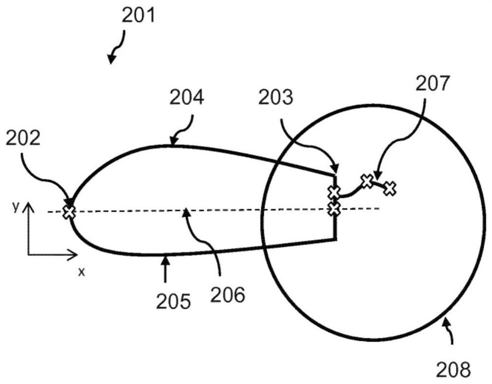
[0044] figure 2 A profile section through a rotor blade of a wind energy installation 106 is schematically shown. In this case, the rotor blade 201 has a contour bead 202 and a trailing edge 203 . For this profile, the trailing ed...


PUM


Abstract

The invention relates to a rotor blade of a wind turbine, the rotor blade (201) having, in particular, a splitter plate (207, 301, 401, 501, 601), which is arranged on the blunt trailing edge (203, 609) of the rotor blade (201). The splitter plate (207, 301, 401, 501, 601) comprises: a root edge (302, 402, 502, 602), the root edge (302, 402, 502, 602) being arranged on, in particular along the trailing edge (203, 609), below a transition of the suction side (204) into the trailing edge (203, 609); an end edge (303, 403, 503, 603), the end edge (303, 403, 503, 603) forming a free edge; and a surface between the root edge (302, 402, 502, 602) and the end edge (303, 403, 503, 603), the surface having at least one curved part between the root edge (302, 402, 502, 602) and the end edge (303, 403, 503, 603), and at least one part of the surface lying in the shear layer produced by the suction side (204).

Description

technical field [0001] The invention relates to a rotor blade of a wind energy installation, a wind energy installation having the rotor blade, a deflector for use on the rotor blade and a method for optimizing the rotor blade. Background technique [0002] Wind energy installations that generate electrical energy from the kinetic energy of the wind and feed the electrical energy into the grid are generally known. Currently, rotor blades with a thin plate-like profile and a large blade depth are often used in such wind energy installations in order to increase the efficiency. However, this requires a multi-piece construction with trailing edge sections, which is very costly and prone to failure. Alternatively, rotor blades with an at least partially blunt trailing edge can be used in the inner region. However, rotor blades with an at least partially blunt trailing edge have the disadvantage that, due to the smaller blade depth, the lift power is reduced in the region of th...

Claims


Application Information

Patent Timeline
Patent Type & Authority Applications(China)
IPC IPC(8): F03D1/06
CPCF03D1/0641F05B2240/31Y02E10/72F05B2240/304F05B2240/305F03D1/0675F05B2240/21
Inventor 斯特凡·克奈斯尔约亨·施滕贝格
Owner WOBBEN PROPERTIES GMBH
Why Eureka
Try Eureka