
Light-emitting assembly and light-emitting module

A technology of light-emitting components and light-emitting modules, applied in static indicators, instruments, etc., can solve problems such as low accuracy

Active Publication Date: 2020-09-29
SHANGHAI TIANMA MICRO ELECTRONICS CO LTD
View PDF5 Cites 4 Cited by
  • Summary
  • Abstract
  • Description
  • Claims
  • Application Information

AI Technical Summary

Problems solved by technology

[0003] However, at present, the accuracy of controlling the gray scale of the light-emitting element is low

Method used


Image

  • Light-emitting assembly and light-emitting module
  • Light-emitting assembly and light-emitting module
  • Light-emitting assembly and light-emitting module

Examples


Embodiment Construction

[0023] The characteristics and exemplary embodiments of various aspects of the present invention will be described in detail below. In order to make the purpose, technical solutions and advantages of the present invention more clear, the present invention will be further described in detail below in conjunction with the accompanying drawings and embodiments. It should be understood that the specific embodiments described here are only configured to explain the present invention, not to limit the present invention. It will be apparent to one skilled in the art that the present invention may be practiced without some of these specific details. The following description of the embodiments is only to provide a better understanding of the present invention by showing examples of the present invention.

[0024] It should be noted that in this article, relational terms such as first and second are only used to distinguish one entity or operation from another entity or operation, and ...


PUM


Abstract

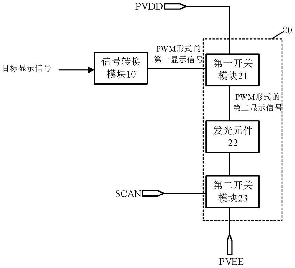
The invention discloses a light-emitting assembly and a light-emitting module. The light-emitting assembly comprises a signal conversion module and a light-emitting unit. The light-emitting unit comprises a first switch module, a light-emitting element and a second switch module, the first end of the first switch module is connected with the signal conversion module, and the second end of the first switch module is connected with the first power supply end; the light-emitting assembly and the second switch module which are connected in series are arranged between the third end of the first switch module and the second power supply end; the signal conversion module is used for converting a target display signal representing image information of a to-be-displayed image block corresponding tothe light emitting unit into a first display signal; wherein the first display signal is used for controlling the third end of the first switch module to output a second display signal in a pulse width modulation form corresponding to the first display signal, and the second display signal is used for controlling the brightness of the light-emitting element under the condition that the scanning end controls the second switch module to be in an on state. The accuracy of brightness control of a light-emitting element can be improved.

Description

technical field [0001] The invention relates to the field of display technology, in particular to a light-emitting component and a light-emitting module. Background technique [0002] Currently, various display devices for displaying information are being developed. In order to improve the display effect of images, whether it is a backlight light-emitting element in a liquid crystal display or a light-emitting element in a self-luminous display panel, it is necessary to control the brightness (ie, gray scale) of the light-emitting element. [0003] However, the accuracy of controlling the gray scale of the light emitting element is relatively low at present. Contents of the invention [0004] Embodiments of the present invention provide a light-emitting component and a light-emitting module, which can accurately control the brightness of the light-emitting element. [0005] In a first aspect, the present application provides a light-emitting assembly, the light-emitting ...

Claims


Application Information

Patent Timeline
Patent Type & Authority Applications(China)
IPC IPC(8): G09G3/34G09G3/30
CPCG09G3/3406G09G3/30
Inventor 东强王丽花孙晓平马从华
Owner SHANGHAI TIANMA MICRO ELECTRONICS CO LTD
Learn More