buckle
What is Al technical title?
Al technical title is built by PatSnap Al team. It summarizes the technical point description of the patent document.
一种带扣、带宽的技术,应用在带扣、扣件、服饰等方向,能够解决没有出现等问题,达到装拆操作简单的效果
Active Publication Date: 2022-05-31
YKK CORP
View PDF9 Cites 0 Cited by
Summary
Abstract
Description
Claims
Application Information
AI Technical Summary
This helps you quickly interpret patents by identifying the three key elements:
Problems solved by technology
Method used
Benefits of technology
Problems solved by technology
Although it is believed that there are various needs for buckles depending on the application, there has not been a buckle that focuses on the ease of attachment and detachment.
Method used
Image
Click on the blue label to locate the original text in one second.
Reading with bidirectional positioning of images and text.
Examples
no. 1 approach >
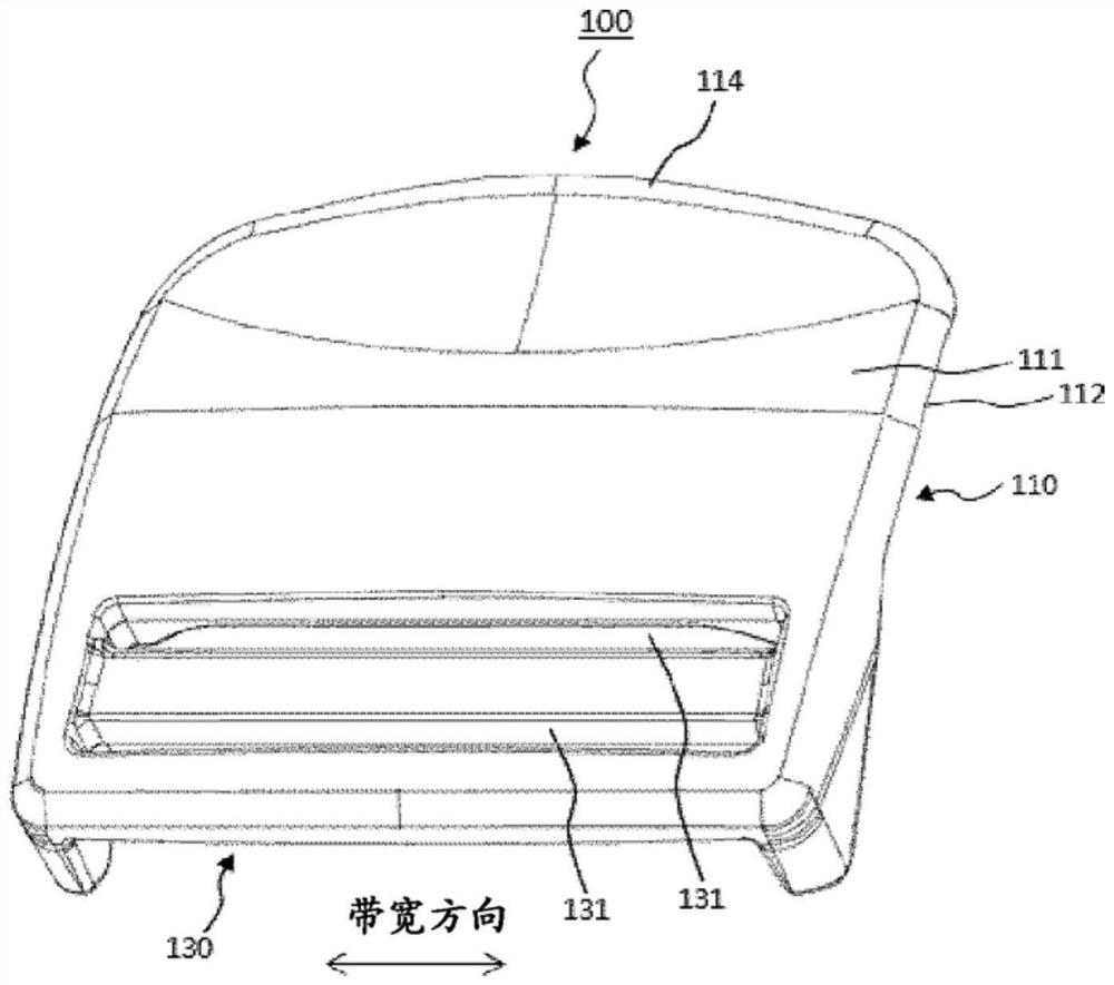
[0052] The secondary surface (111) of the male part (100) of the buckle (10) of the first embodiment of the present invention is shown in Figure 1-1
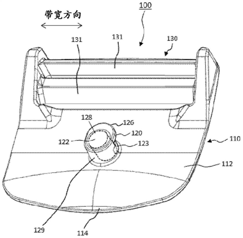
[0054] The male member (100) of the buckle (10) of the present embodiment includes: a first surface (111) and a back surface (112)
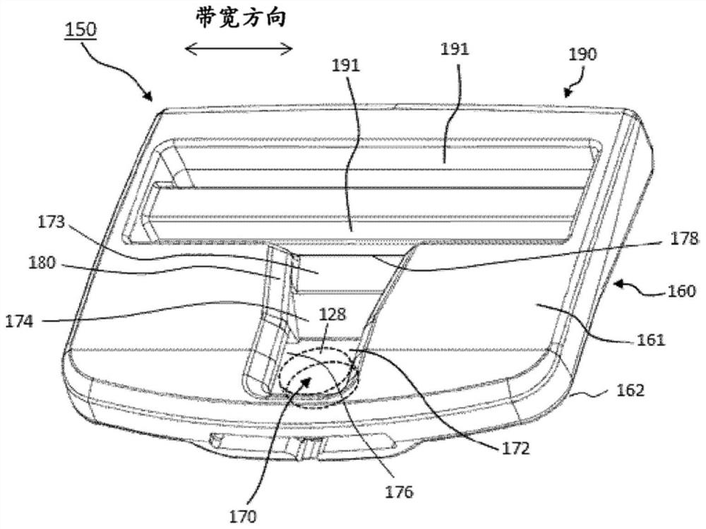
[0055] The female member (150) of the buckle (10) of the present embodiment is provided with: a second
[0056] In the female member (150) of the buckle (10) of the present embodiment, one of the protruding portion (120) and the recessed portion (170) is provided.
[0057] The material of the male member (100) and the female member (150) is not particularly limited, for example, other than metal, it can also be
[0059] The recessed portion (170) of the female member (150) has a claw receiving portion (176) capable of engaging with the claw portion (126). from the surface
[0062] The female member (150) of the buckle (10) of the present embodiment has a surface (161) to which the second plate-shaped b...
no. 2 approach >
[0093] If the inclination angle of the slope (124) with respect to the top surface (122) is small, the male part and the female part can be smoothly performed
[0094] The above-mentioned slope may be formed only in one of the protruding portion (120) and the recessed portion (170), but may also be formed in
[0096] Also in the buckle (10) of the present embodiment, a card that maintains the engagement between the claw portion (126) and the claw receiving portion (176) is maintained.
[0097] In the buckle (10) of the present embodiment, the recessed portion seen when the female member (150) is viewed from the surface (161) side
no. 3 approach >
[0100] The female part (150) of the third embodiment does not have slopes (124, 174), which is different from the female part (150) of the second embodiment.
PUM
Abstract
Provided is a buckle which improves the degree of freedom in attaching and detaching operations. The buckle is provided with a male part and a female part, the male part has a protrusion, the female part has a recess capable of engaging with the male part, and the female part has a surface and a recess for connecting the second plate-shaped base to the above-mentioned protrusion. The inclined surface leading to the concave part, the above-mentioned protruding part has a claw part, the above-mentioned concave part has a claw receiving part that can engage with the above-mentioned claw part, and the contour of the claw receiving part seen when the female part is viewed from the surface side is toward the second Two protruding polygonal lines or curved lines on the opposite side of the mounting part, a magnet is embedded in one of the above-mentioned protrusions and the above-mentioned recessed parts, and a magnet is embedded in the other to be attracted by the above-mentioned magnet. magnets or metals that are attracted to such magnets.
Description
buckle technical field [0001] The present invention relates to a buckle utilizing a magnet. Background technique [0002] Conventionally, not only for belts, but also for bags, backpacks, clothes, shoes, helmets, sporting goods and packaging equipment, etc. The ends of the straps attached to the article are connected to each other, and a strap that engages the male member and the female member detachably is used. buckle. In such a belt buckle, on the one hand, the operation for attaching and detaching is required to be simple, and on the other hand, it is required to avoid accidents when unintentional fall off. Conventionally, in order to satisfy such required characteristics, various buckle structures have been proposed. [0003] In Japanese Unexamined Publication No. Sho 62-119815 (Patent Document 1), a buckle is described, which is composed of a first connecting portion. and a second connecting member that can be engaged and disengaged with respect to the first co...
Claims
Application Information
Patent Timeline
Application Date:The date an application was filed.
Publication Date:The date a patent or application was officially published.
First Publication Date:The earliest publication date of a patent with the same application number.
Issue Date:Publication date of the patent grant document.
PCT Entry Date:The Entry date of PCT National Phase.
Estimated Expiry Date:The statutory expiry date of a patent right according to the Patent Law, and it is the longest term of protection that the patent right can achieve without the termination of the patent right due to other reasons(Term extension factor has been taken into account ).
Invalid Date:Actual expiry date is based on effective date or publication date of legal transaction data of invalid patent.