Belt buckle
A belt buckle and bandwidth technology, applied in the direction of belt buckles, fasteners, clothing, etc., can solve the problem of no occurrence, and achieve the effect of simple assembly and disassembly operation and simple assembly and disassembly operation.
- Summary
- Abstract
- Description
- Claims
- Application Information
AI Technical Summary
Problems solved by technology
Method used
Image

Examples
no. 1 approach >
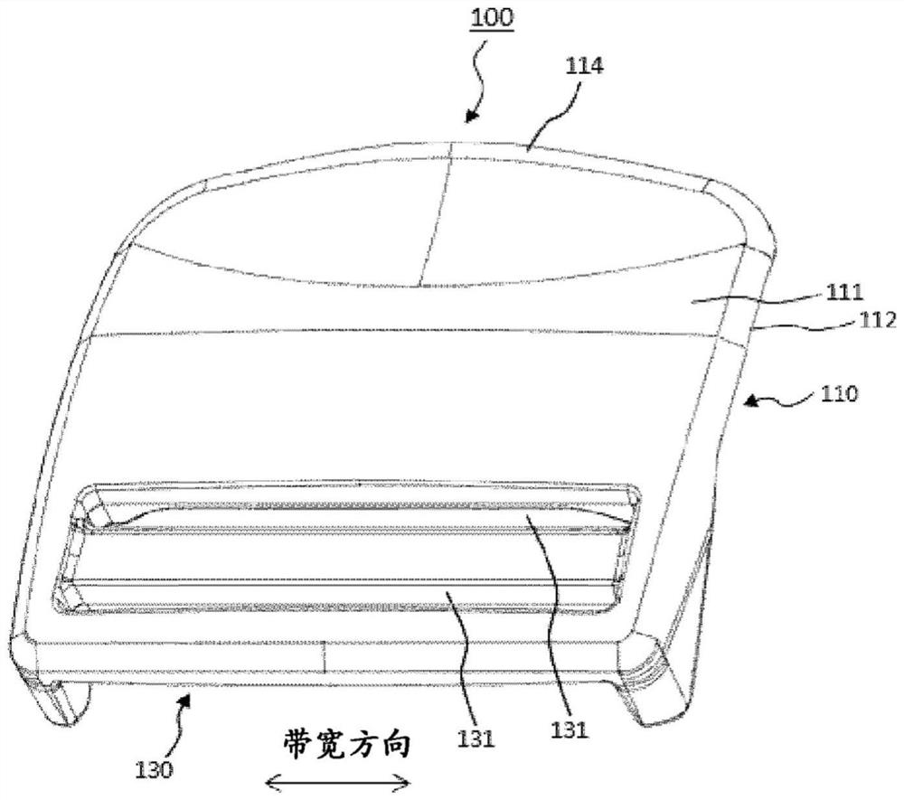
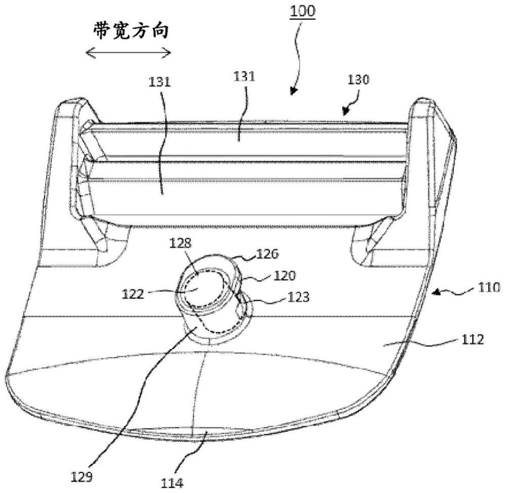
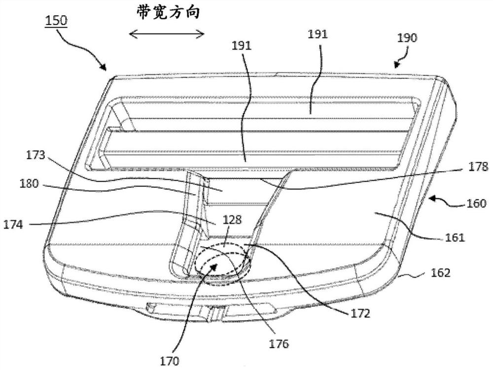
[0047] Picture 1-1 is a perspective view of the male part (100) of the buckle (10) according to the first embodiment of the present invention viewed from the surface (111) side. Figure 1-2 is a perspective view of the male part (100) of the buckle (10) according to the first embodiment of the present invention as viewed from the rear (112) side. diagram 2-1 is a perspective view of the female part (150) of the buckle (10) according to the first embodiment of the present invention viewed from the surface (161) side. Figure 2-2 is a perspective view of the female part (150) of the buckle (10) according to the first embodiment of the present invention viewed from the back side (162). image 3 is a perspective view when the male part (100) and the female part (150) of the buckle (10) according to the first embodiment of the present invention are engaged.
[0048] (1-1. Overall structure)
[0049] The male part (100) of the buckle (10) of this embodiment includes: a first pla...
no. 2 approach >
[0086] Figure 5 is a perspective view of the male part (100) of the buckle according to the second embodiment of the present invention viewed from the back side. Image 6 is a perspective view of the female part (150) of the buckle according to the second embodiment of the present invention viewed from the surface side. exist Figure 5 and Image 6 Herein, constituent elements denoted by the same reference numerals as those of the first embodiment denote the same constituent elements as those of the first embodiment, and detailed description thereof will be omitted. Hereinafter, differences between the second embodiment and the first embodiment will be described.
[0087] In the buckle (10) of this embodiment, the protruding portion (120) has a top surface (122) and a slope (124) connected to the top surface (122) and descending toward the opposite side of the first belt mounting portion (130). ). Like the slope (174) of the recessed portion (170) described in the first ...
no. 3 approach >
[0094] Figure 7 is a perspective view of the buckle female part (150) according to the third embodiment of the present invention as viewed from the surface side. Figure 7 In the description, the constituent elements denoted by the same reference numerals as those of the first embodiment denote the same constituent elements as those of the first embodiment, and detailed description thereof will be omitted. In addition, since the male part (100) of the buckle of 3rd Embodiment is the same as 1st Embodiment, the description is abbreviate|omitted.
[0095] The female part (150) of the third embodiment does not have slopes (124, 174), which is different from the female part of the second embodiment in this aspect, and other structures are the same as the female part of the second embodiment. In the buckle female part (150) of the third embodiment, at the end of the first bottom surface (172) on the side of the second belt mounting portion (190), instead of the slope (174), a (1...
PUM
 Abstract
Description
Claims
Application Information
 - R&D
- Intellectual Property
- Life Sciences
- Materials
- Tech Scout
- Unparalleled Data Quality
- Higher Quality Content
- 60% Fewer Hallucinations
Browse by: Latest US Patents, China's latest patents, Technical Efficacy Thesaurus, Application Domain, Technology Topic, Popular Technical Reports.
© 2025 PatSnap. All rights reserved.Legal|Privacy policy|Modern Slavery Act Transparency Statement|Sitemap|About US| Contact US: help@patsnap.com