
Air spring damping device and damping method thereof

A technology of air springs and shock absorbers, applied in the direction of springs/shock absorbers, springs, shock absorbers, etc., can solve problems such as equipment damage, reduce the influence of natural vibration, reduce the area of ​​natural vibration, and reduce the structure damage effect

Inactive Publication Date: 2021-11-16
HANGZHOU DIANZI UNIV
View PDF5 Cites 0 Cited by
  • Summary
  • Abstract
  • Description
  • Claims
  • Application Information

AI Technical Summary

Problems solved by technology

[0003] The purpose of the present invention is to propose an air spring damping device and its damping method for the problem that the excessively large natural vibration area of ​​the air spring may cause damage to the inside of the equipment

Method used


Image

  • Air spring damping device and damping method thereof
  • Air spring damping device and damping method thereof
  • Air spring damping device and damping method thereof

Examples


Embodiment 1

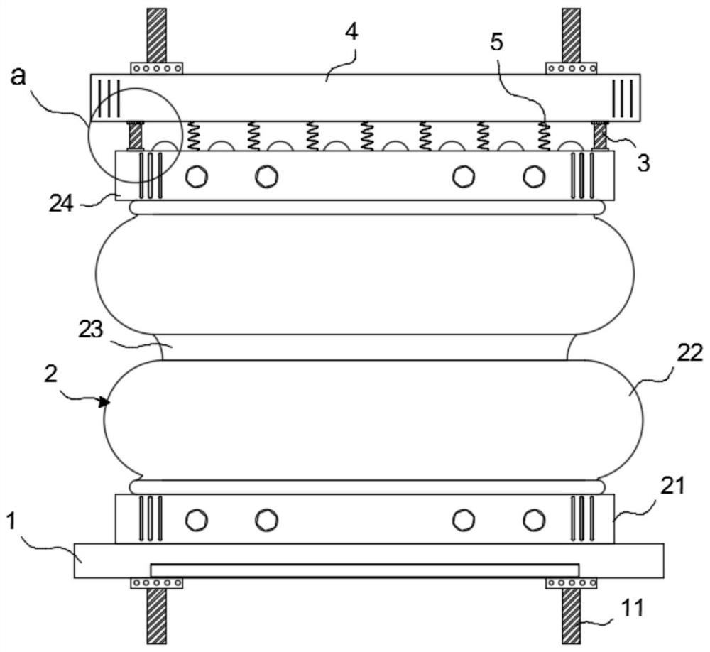
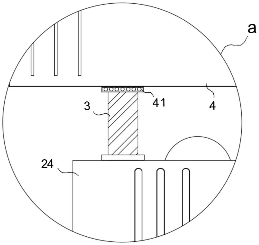
[0025] refer to figure 1 and figure 2 , an air spring damping device, comprising a base connecting plate 1, an air spring body 2, a shock absorbing screw 3 and a top connecting plate 4; several connecting pieces 11 are fixed on the base connecting plate 1 and the top connecting plate 4, the connecting pieces 11. The connecting screw can be selected, and the air spring damping device can be assembled in the related equipment through the connection between the nut and the connecting screw; Screw holes and a damping screw rod 3 form a screw pair; the outer rings of n bearings 41 are fixed with the top connecting plate 4, and the inner rings of n bearings 41 are fixed with n damping screw rods 3 respectively.

Embodiment 2

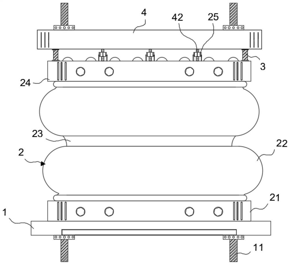
[0027] This embodiment is limited on the basis of Embodiment 1. The air spring body 2 includes a bottom end seal plate 21, an air flexure 22 and a top end seal 24; the bottom end seal 21 is fixed to the base connecting plate 1; several air flexures 22 are provided, and two adjacent air flexures 22 communicates through the waist ring 23, the air flexure 22 closest to the bottom end seal 21 is glued to the bottom end seal 21, and the air flexure 22 closest to the top end seal 24 is glued to the top end seal 24. The n screw holes that form the helical pair with the n damping screw rods 3 are all opened on the top end sealing plate 24 .

Embodiment 3

[0029] This embodiment is limited on the basis of the second embodiment. The inner layer of the air bellows 22 is made of high-air-tightness rubber, and the outer layer is made of medium-resistant and aging-resistant rubber.


PUM


Abstract

The invention discloses an air spring damping device and a damping method thereof. The natural vibration area of ​​the existing air spring body is too large. The invention includes a base connecting plate, an air spring body, a shock absorbing screw and a top connecting plate; several connecting pieces are fixed on both the base connecting plate and the top connecting plate; one end of the air spring body is fixed to the base connecting plate, and the other end is provided with a screw holes, and each screw hole forms a screw pair with a damping screw; the outer rings of the n bearings are all fixed to the top connecting plate, and the inner rings of the n bearings are respectively fixed to the n damping screws. In the present invention, the damping screw restricts the position of the air spring body through threaded connection. When the air spring body vibrates naturally, it will only slide on the damping screw, thereby limiting the vibration in the vertical direction of the damping screw and reducing the air pressure. The natural vibration area of ​​the spring.

Description

technical field [0001] The invention relates to an air spring device, in particular to an air spring damping device and a damping method thereof. Background technique [0002] The air spring is filled with compressed air in a sealed container, and uses the compressibility of the gas to realize its elastic effect. The problem with the air spring is that when the air spring body realizes its elastic function, it will also have a self-vibration situation; Damage the internal parts of the equipment and cause unnecessary losses. Contents of the invention [0003] The object of the present invention is to propose an air spring damping device and a damping method thereof for the problem that the excessively large natural vibration area of ​​the air spring may cause damage to the inside of the equipment. [0004] In order to achieve the above object, the present invention adopts the following technical solutions: [0005] An air spring damping device of the present invention co...

Claims


Application Information

Patent Timeline
Patent Type & Authority Patents(China)
IPC IPC(8): F16F3/07F16F15/023F16F15/067
CPCF16F9/0409F16F9/0418F16F13/002F16F15/023F16F15/067
Inventor 李志华沈汉武柴宇君樊志华
Owner HANGZHOU DIANZI UNIV
Learn More