Camera lifting system for cable trench inspection robot

A technology of inspection robot and lifting system, which is applied in the installation of closed-circuit television system, TV system components, cables, etc. It can solve the problems of inspection loopholes, poor monitoring effect of cable temperature change, and complicated operation, so as to ensure that the rod body is straight Straightness, reliable protection effect, and placement reliability effect

Pending Publication Date: 2020-09-08
ELECTRIC POWER RES INST OF STATE GRID ANHUI ELECTRIC POWER +1
View PDF2 Cites 4 Cited by
  • Summary
  • Abstract
  • Description
  • Claims
  • Application Information

AI Technical Summary

Problems solved by technology

However, the disadvantages of thermal wires are: firstly, the cables located on both sides of the cable tunnel are bundled and arranged in bundles, and the thermal wires can only monitor the high temperature changes of the adjacent cables that are close to each other, and the thermal wires located at the farthest end The temperature change monitoring effect of the cable is very poor
The existence of the firewall makes it necessary to repeatedly take out the tunnel inspection robot from the previous tunnel unit-reset the cover plate on the previous tunnel unit-remove the cover plate of the new tunnel unit-replace the tunnel inspection robot every time it inspects the tunnel inspection robot. The process of entering the tunnel inspection robot is extremely complicated and requires a lot of physical labor, which obviously seriously restricts the actual inspection efficiency.
On the other hand, as stated above, the cables in the cable tunnel are arranged in bundles, so there is a certain height. The traditional tunnel inspection robot can inspect the height constant, and there must be some dead ends of the cables that cannot be inspected, resulting in inspection loopholes. ,There are security risks

Method used


Image

  • Camera lifting system for cable trench inspection robot
  • Camera lifting system for cable trench inspection robot
  • Camera lifting system for cable trench inspection robot

Examples


Embodiment Construction

[0045] When the present invention is implemented, it exists as a part of the cable trench inspection robot. Therefore, for the convenience of overall understanding, the structure and working method of the specific embodiment of the entire cable trench inspection robot are described as follows:

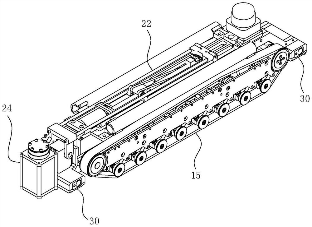
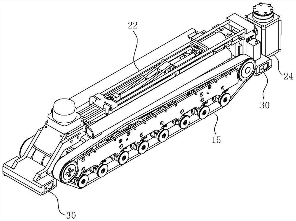
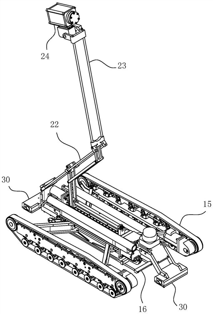
[0046] Cable trench inspection robot, such as Figure 1-17 As shown, its main body includes a base deployment system and a camera lifting system arranged on the base deployment system. in:

[0047] 1. Base expansion system

[0048] Base deployment systems such as Figure 1-12 As shown, it includes an expansion assembly for driving the walking assembly 15 to be extended so as to walk on the ground of the cable tunnel with a traveling posture, and driving the walking assembly 15 to return to the walking state so as to retract the width of the cable trench, and for driving the entire system to lift so that The jacking assembly 16 that is higher than the cable trench and descends so as...


PUM


Abstract

The invention belongs to the technical field of cable inspection, and particularly relates to a camera lifting system for a cable trench inspection robot. The camera lifting system comprises a base and an imitation four-connecting-rod assembly, and a stroke block is arranged on the base; the bottom end of a first rocking bar of the imitation four-connecting-rod assembly extends downwards and is inhinged fit with the stroke block; the bottom end of the first connecting rod is fixedly connected to the position, behind the stroke block, of the end of the base, and the top end of the first connecting rod extends forwards and is in hinged fit with the bottom end of the supporting rod; a first sliding sleeve is hinged to the top end of the first rocking bar and is in sliding rail fit with the first connecting rod; the tail end of a second connecting rod is hinged to the middle section of a rod body of the first rocking bar, the top end of the second connecting rod is hinged to the bottom end of a second rocking bar, and a second sliding sleeve is hinged to the top end of the second rocking bar and is in sliding fit with the supporting rod; and the top of the supporting rod is fixedly connected with a camera assembly. The camera lifting system can provide a basic guarantee for the subsequent through-wall operation of a cable tunnel inspection robot.

Description

technical field [0001] The invention belongs to the technical field of cable inspection, and in particular relates to a camera lifting system for a cable trench inspection robot. Background technique [0002] The occurrence of fires in cable tunnels is a process of gradual accumulation. With the increase of time, due to the aging of the insulation layer, the accumulation of dust and oil, and the looseness of the intermediate joints, the local temperature of the cable will gradually rise, which will cause a fire. Before the accident occurs, if the temperature and smoke inside the cable tunnel can be effectively monitored in real time, the fire can be prevented before it happens. Although the monitoring problem of cable tunnel has attracted people's attention, but has not found a proper and reasonable solution. [0003] Traditional cable tunnels are manually inspected. At regular intervals, inspectors enter the tunnel and use temperature measuring instruments to manually ch...

Claims


Application Information

Patent Timeline
Patent Type & Authority Applications(China)
IPC IPC(8): B25J11/00B25J19/00H02G1/00H04N5/232H04N7/18
CPCB25J11/00B25J19/00H02G1/00H04N7/185H04N23/695
Inventor 孙韬肖波谢佳范明豪董翔宇张佳庆尚峰举叶良鹏章彬彬程宜风
Owner ELECTRIC POWER RES INST OF STATE GRID ANHUI ELECTRIC POWER
Why Eureka
Try Eureka