Grid ruler for grid spraying and scribing

A technology of grid and main board, applied in the field of grid ruler, can solve the problems of slow speed and low precision

Pending Publication Date: 2020-09-04
TIANJIN UNIV
View PDF0 Cites 0 Cited by
  • Summary
  • Abstract
  • Description
  • Claims
  • Application Information

AI Technical Summary

Problems solved by technology

[0005] Aiming at the disadvantages of the existing grid marking speed and low precision, the present invention provides a grid ruler specially used for grid marking

Method used


Image

  • Grid ruler for grid spraying and scribing
  • Grid ruler for grid spraying and scribing
  • Grid ruler for grid spraying and scribing

Examples


Embodiment Construction

[0031] Below in conjunction with accompanying drawing, specific embodiment is further described:

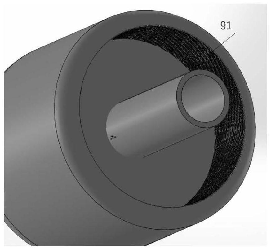
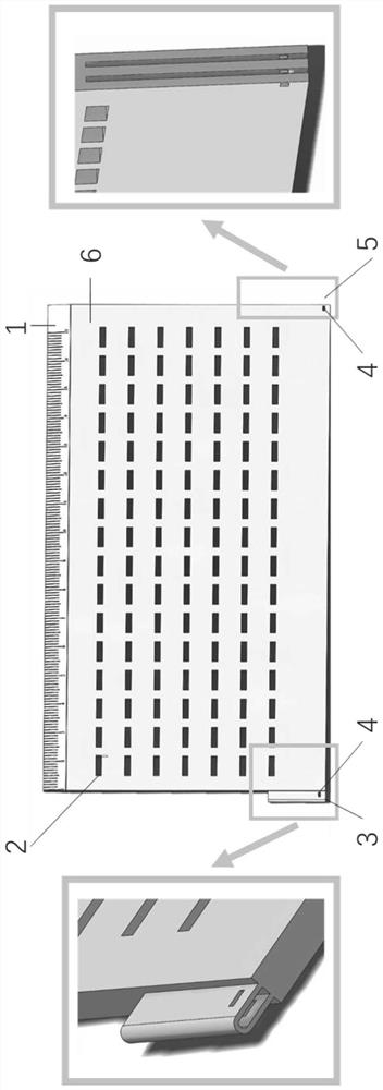
[0032] The grid ruler of the present invention is used in combination with another special tool, the grid spray tank, to realize grid painting that is efficient, accurate and can save paint. Figure 1-Figure 4 is the grid ruler part, Figure 5-Figure 11 Spray tank sections for grids with exchangeable spray heads, Figure 12 Draw a schematic diagram of the method for the mesh.

[0033] grid ruler

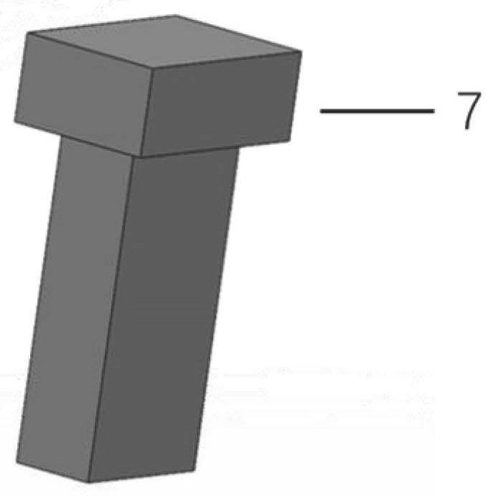
[0034] The grid ruler is realized in the following way: construct a grid ruler, including a measuring section 1, a hole array 2, a left connector 3, a connecting hole 4, a right connector 5, a main board 6, and a special pin 7.

[0035] The measurement section 1 is located on the main board 6. From left to right, the scale is from 0 to 17cm. The scale line at each full centimeter is the longest, and the length of the scale line at every 5mm scale is second, which is convenient for ob...


PUM


Abstract

The invention relates to a grid ruler for grid spraying and scribing. The grid ruler comprises a main body plate and a measuring section, and is characterized in that a hole site array is formed in the main body plate, the hole sites are rectangles with the same size, the hole length direction is set as a row, the hole width direction is set as a column, row spacings are equal, the measuring section with scales is arranged on one side edge of the main body plate, and the measuring section is parallel to the hole length direction. The grid ruler can be used for realizing efficient and high-precision drawing of grid scribing.

Description

technical field [0001] The invention relates to a grid ruler used for grid spraying and scribing. Background technique [0002] Grid is a commonly used method of measurement and calculation in the field of engineering research, and it has been widely used in experiments and numerical simulations. Commonly used T-shaped steel, I-beam, flat steel, masonry structure, etc., after torsion, crushing, bending and other deformations, in order to measure the specific deformation value, it is usually calculated by borrowing the deformation of the grid. Therefore, it is necessary to complete the grid marking work before the test. [0003] The actual work of marking the line needs to use the traditional method, first measure with a ruler, then mark the position, and then connect each point, draw one surface, and then draw another surface that needs to be aligned with it, usually a 4-meter-long For steel pipes, it takes about 30 minutes to complete the grid marking, and the overall tim...

Claims


Application Information

Patent Timeline
IPC IPC(8): B05B12/20
CPCB05B12/20
Inventor 余建星李昊达余杨王华昆王彩妹
Owner TIANJIN UNIV
Why Eureka
Try Eureka