
Operation joint capable of being installed on insulating rod

A technology of insulating rods and vertical rods, which is applied in the field of operating joints, can solve the problems of inconvenient clamping and pushing and pulling of electrical components, adjustment of structural characteristics of operating joints, inconvenience and other problems, and achieves convenient and fast connection operations, simple installation and disassembly operations, Ease of use

Pending Publication Date: 2020-09-01
HUNAN CHINA RESOURCES POWER LIYUJIANG CO LTD
View PDF0 Cites 0 Cited by
  • Summary
  • Abstract
  • Description
  • Claims
  • Application Information

AI Technical Summary

Problems solved by technology

[0004] The purpose of the present invention is to provide an operating joint that can be installed on an insulating rod, so as to solve the problem that the end of the insulating operating rod on the market is not convenient to be provided with a mechanism for clamping and pushing and pulling each electrical component, which must be repaired by maintenance. Maintenance operations can only be carried out by personnel going up, and at the same time, the existing operating joints are inconvenient to be connected and fixed with insulating rods of different thicknesses. In addition, there is also the problem that it is not convenient to adjust the structural characteristics of the operating joints according to actual usage conditions

Method used


Image

  • Operation joint capable of being installed on insulating rod
  • Operation joint capable of being installed on insulating rod
  • Operation joint capable of being installed on insulating rod

Examples


Embodiment Construction

[0020] The following will clearly and completely describe the technical solutions in the embodiments of the present invention with reference to the accompanying drawings in the embodiments of the present invention. Obviously, the described embodiments are only some, not all, embodiments of the present invention. Based on the embodiments of the present invention, all other embodiments obtained by persons of ordinary skill in the art without making creative efforts belong to the protection scope of the present invention.

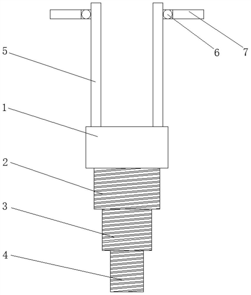
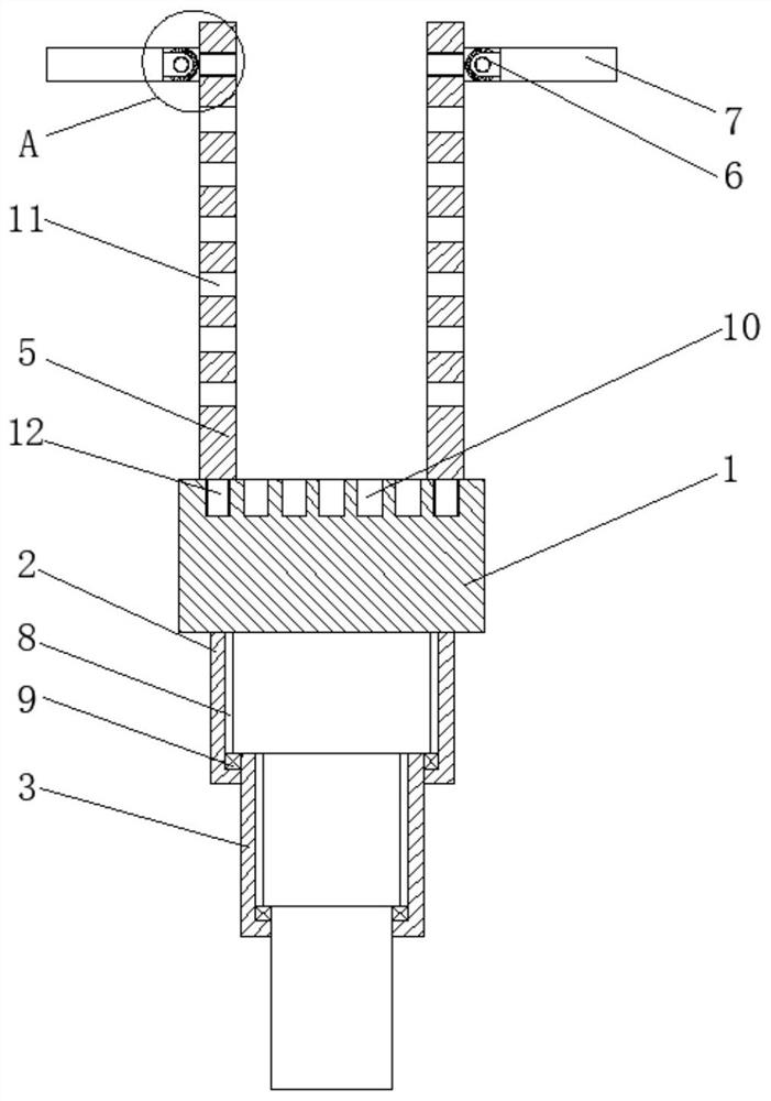
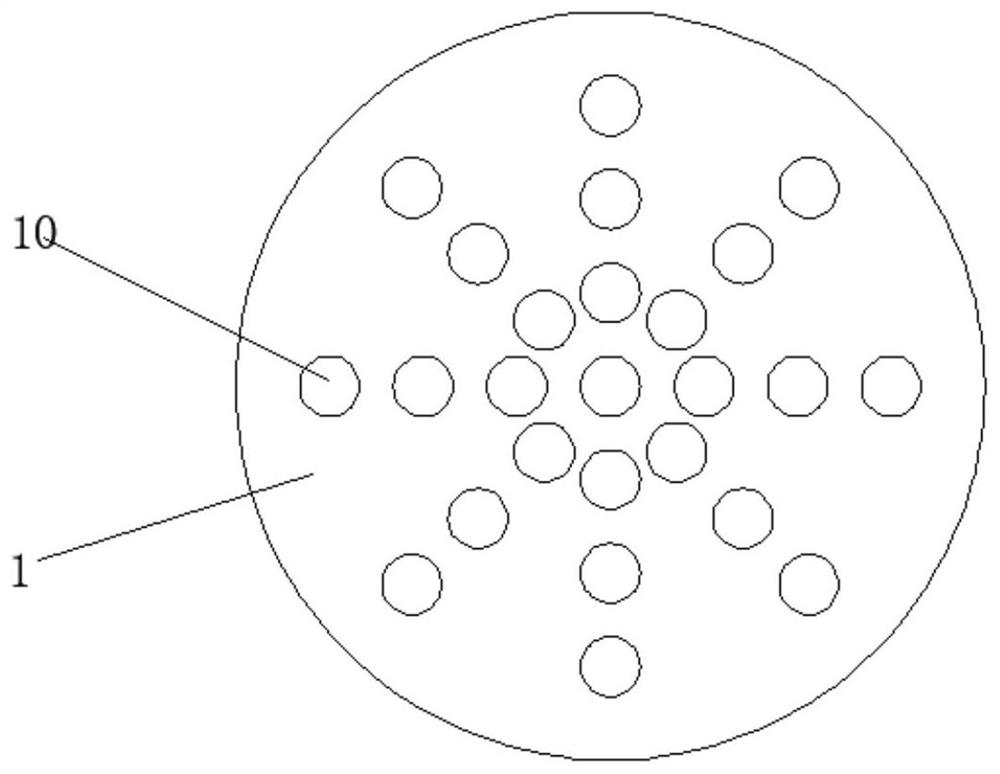
[0021] see Figure 1-4 , the present invention provides a technical solution: an operating joint that can be installed on an insulating rod, including a base 1, a first connecting cylinder 2, a second connecting cylinder 3, a third connecting cylinder 4, a vertical rod 5, an angle adjustment assembly 6, a fixed Rod 61, sleeve plate 62, clamping block 63, clamping groove 64, cross bar 7, chute 8, slide block 9, first screw hole 10, second screw hole 11 and scre...


PUM


Abstract

The invention discloses an operation joint capable of being installed on an insulating rod. The operation joint comprises a base, a vertical rod and a cross rod, a first connecting cylinder is fixed below the base, and the lower part of the first connecting cylinder is connected with a second connecting cylinder. A third connecting cylinder is mounted below the second connecting cylinder, the vertical rods are installed at the left side and the right side of the upper portion of the base correspondingly, and the outer side of the top end of the vertical rod is connected with an angle adjustingassembly. The cross rod is mounted at one side, far away from the vertical rod, of the angle adjusting assembly, the angle adjusting assembly comprises a fixed rod, a sleeve plate, clamping blocks and clamping grooves, and the sleeve plate sleeves the fixed rod. The clamping blocks are evenly fixed to the outer edge at the right side of the sleeve plate, the clamping grooves are formed at the outer sides of the clamping blocks, sliding grooves are formed on the inner walls at the left side and the right side of the first connecting cylinder, and the sliding blocks are arranged in the slidinggrooves. The operation joint capable of being installed on the insulating rod can be fixedly connected with three insulating operating rods with different diameters, so that the application range of the whole operation joint is greatly expanded.

Description

technical field [0001] The invention relates to the technical field of circuit maintenance tools, in particular to an operating joint that can be installed on an insulating rod. Background technique [0002] At present, when the power supply line is being maintained, various electrical components and switches installed on the high-voltage distributor in the air cannot be directly operated by hand, so an insulating operating rod is used, which is a unified set of insulating tools specially used in the power system The appellation can be used for live work, live maintenance and live maintenance work equipment, such as turning on or off high-voltage isolating switches, dropping fuses, etc. [0003] However, the ends of insulating operating rods currently on the market are not convenient for setting up mechanisms for clamping and pushing and pulling various electrical components, and maintenance personnel must go up to perform maintenance operations. At the same time, the existi...

Claims


Application Information

Patent Timeline
Patent Type & Authority Applications(China)
IPC IPC(8): H02B3/00H02G1/00H01H3/02H01H85/02H01H85/25H01R43/26
CPCH01H3/02H01H85/0208H01H85/25H01R43/26H02B3/00H02G1/00
Inventor 沈露陈定伟潘大端兰海涛
Owner HUNAN CHINA RESOURCES POWER LIYUJIANG CO LTD
Learn More