
Bogie connecting device and process bogie set

A technology of a process bogie and a connecting device, applied in the field of connecting equipment, can solve problems such as the disengagement of the card slot and the separation of the two process bogies.

Inactive Publication Date: 2020-08-25
GUANGZHOU INST OF RAILWAY TECH
View PDF1 Cites 0 Cited by
  • Summary
  • Abstract
  • Description
  • Claims
  • Application Information

AI Technical Summary

Problems solved by technology

[0005] The present invention provides a bogie connection device and a process bogie group in order to solve the technical problem that the existing connection device in the above-mentioned background technology may be disengaged at the slot, thereby resulting in the separation of the two process bogies

Method used


Image

  • Bogie connecting device and process bogie set
  • Bogie connecting device and process bogie set
  • Bogie connecting device and process bogie set

Examples


Embodiment 1

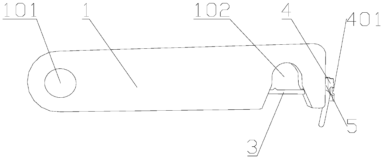
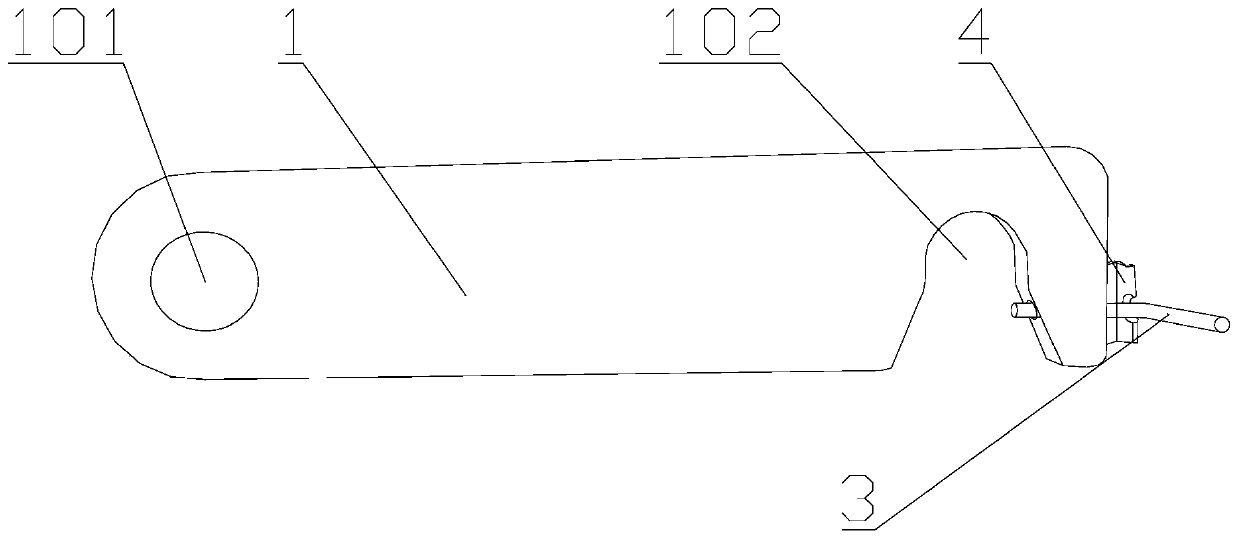
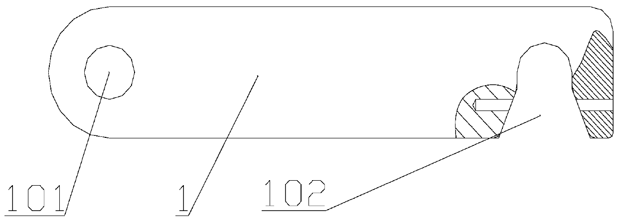
[0044] Such as Figure 1 to Figure 4 As shown, the present invention provides a bogie connecting device, which includes a vertically arranged block body 1, an L-shaped connecting rod 3, an anti-off baffle 4 and a connecting plate 5, wherein: one end of the block body 1 is provided with A through hole 101 that runs through front and rear, a slot 102 is provided on the bottom of the other end of the block-shaped main body 1, and the other end of the block-shaped main body 1 is fixedly connected with one end of the connecting plate 5, and the block-shaped main body The other end of 1 is provided with a through hole arranged along the length direction of the block body 1; the other end of the connecting plate 5 is fixedly connected with one end of the anti-off baffle 4, and the anti-off baffle 4 The other end of the front and rear is provided with a front and rear through groove 401, the groove 401 is connected with the slot 102 through the through hole, and the anti-falling baffl...

Embodiment 2

[0050] The difference from Example 1 is that, as Figure 5 and Figure 6 As shown, a process bogie group is provided, including the bogie connecting device as described in Embodiment 1, the first process bogie 8, the second process bogie 9 and the nut 6, wherein: the first process bogie The frame 8 is fixed with a vertically arranged screw rod 801, and the screw rod 801 is movably socketed with the through hole 101 on the block body 1 and then threadedly connected with the nut 6; the second process bogie 9 is fixed with a vertically arranged fixing column 901 , the fixing column 901 is engaged with the slot 102 and is located in the closed space formed by the slot 102 and the L-shaped connecting rod 3 .

[0051] Optionally, the side wall of the L-shaped connecting rod 3 abuts against the side wall of the fixing column 901 .

[0052] Optionally, a washer 2 is further included, and the washer 2 is socketed on the bolt 801 and located between the block body 1 and the nut 6 .

...


PUM


Abstract

The invention belongs to the field of connecting equipment, and particularly relates to a bogie connecting device and a process bogie set. The bogie connecting device comprises a vertically-arranged blocky main body, an L-shaped connecting rod, an anti-falling baffle, a connecting plate and a nut. The process bogie set comprises a first process bogie, a second process bogie, the nut and the bogieconnecting device. The blocky main body is movably connected with a screw rod on the first process bogie through a through hole; the blocky main body is clamped with a fixed column on the second process bogie through an open groove and is fixed through an L-shaped connecting rod; the first process bogie and the second process bogie can form a process bogie group to move freely through the bogie connecting device; and due to the fixing effect of the L-shaped connecting rod, the first process bogie and the second process bogie are prevented from being separated, and a technical problem that an existing connecting device may be disengaged at a clamping groove so that the two process bogies are separated is solved.

Description

technical field [0001] The invention belongs to the field of connection equipment, and in particular relates to a bogie connection device and a process bogie group. Background technique [0002] Two different process bogies form a process bogie group, and the two different process bogies need to be connected in the middle, so that the process bogies can run together to play the role of steering. [0003] At present, the connecting device between the process bogies is generally connected by a connecting plate. The frame is detachably connected through the card slot, and this structure can realize the rotational connection of the two process bogies. [0004] However, when the existing connecting device moves in the process bogie group, if the gap at the joint of the rails is large or the height difference between the two process bogies is large, the connecting device may be disengaged at the clamping groove, thereby Resulting in the separation of the two process bogies. Co...

Claims


Application Information

Patent Timeline
IPC IPC(8): B61F5/52F16B19/02
CPCB61F5/52F16B19/02
Inventor 李涛陈选民陆超叶会志秦财亿凌秋生王腾
Owner GUANGZHOU INST OF RAILWAY TECH
Learn More