
Rotation control mechanism of rotary welding device

A technology of rotary welding and control mechanism, which is applied to auxiliary devices, welding equipment, auxiliary welding equipment, etc., can solve the problems that the operation method is not convenient and comfortable, and affect the use of the rotary control mechanism, so as to achieve convenient operation and use, and convenient angle. The effect of adjusting and improving comfort

Inactive Publication Date: 2020-08-18
HUANGSHI HENGSHENG TECH CO LTD
View PDF12 Cites 1 Cited by
  • Summary
  • Abstract
  • Description
  • Claims
  • Application Information

AI Technical Summary

Problems solved by technology

[0004] The purpose of the present invention is to provide a rotation control mechanism of a rotary welding device to solve the problem of the rotation control mechanism of a conventional rotary welding device currently on the market proposed in the above-mentioned background technology. In the process of using it, the staff manually During the rotation operation, the operation method is not convenient and comfortable enough, which affects the staff's use of the rotation control mechanism.

Method used


Image

  • Rotation control mechanism of rotary welding device
  • Rotation control mechanism of rotary welding device
  • Rotation control mechanism of rotary welding device

Examples


Embodiment Construction

[0020] The following will clearly and completely describe the technical solutions in the embodiments of the present invention with reference to the accompanying drawings in the embodiments of the present invention. Obviously, the described embodiments are only some, not all, embodiments of the present invention. Based on the embodiments of the present invention, all other embodiments obtained by persons of ordinary skill in the art without making creative efforts belong to the protection scope of the present invention.

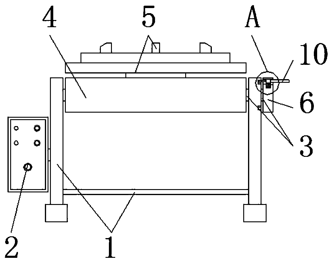
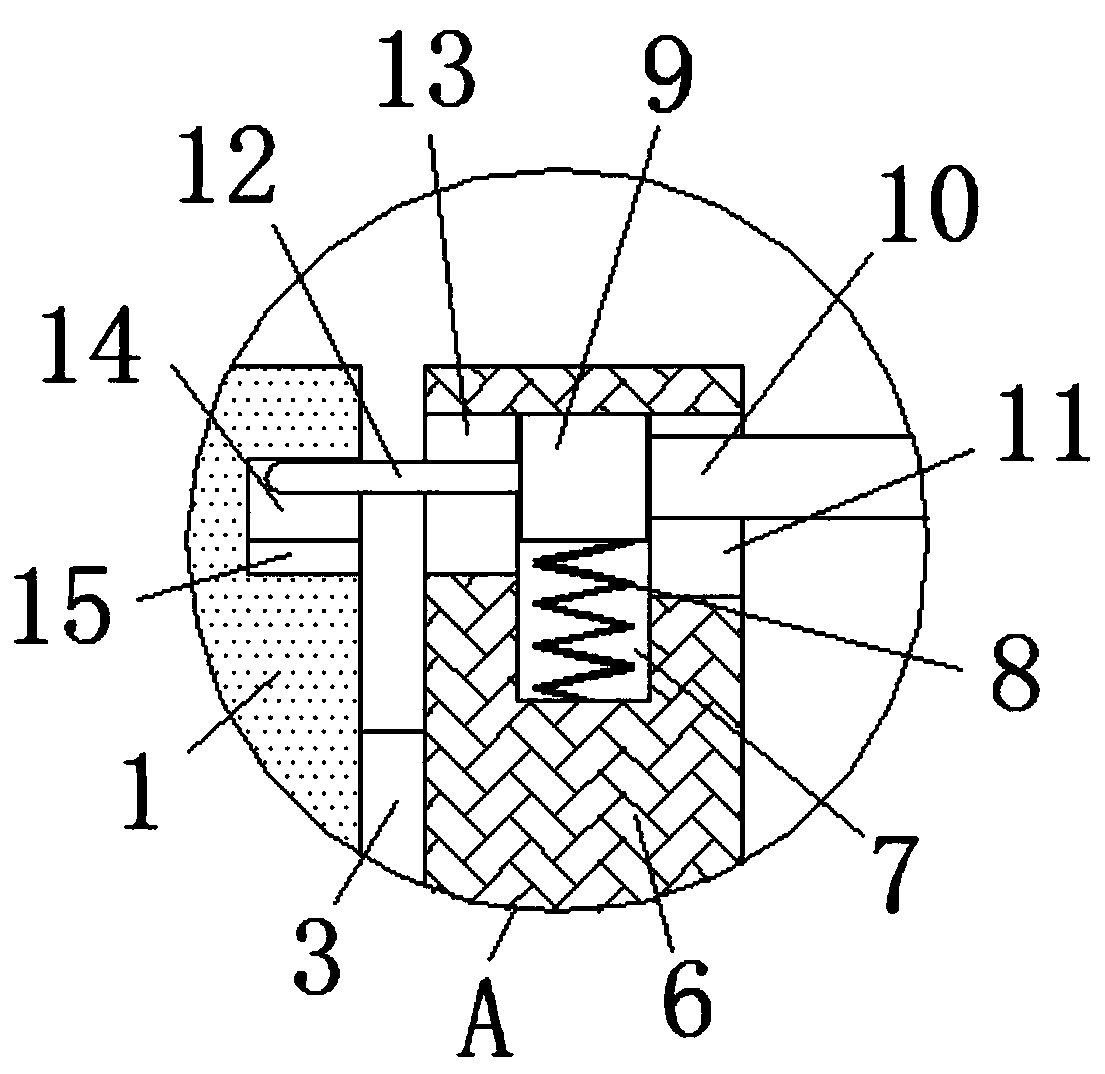
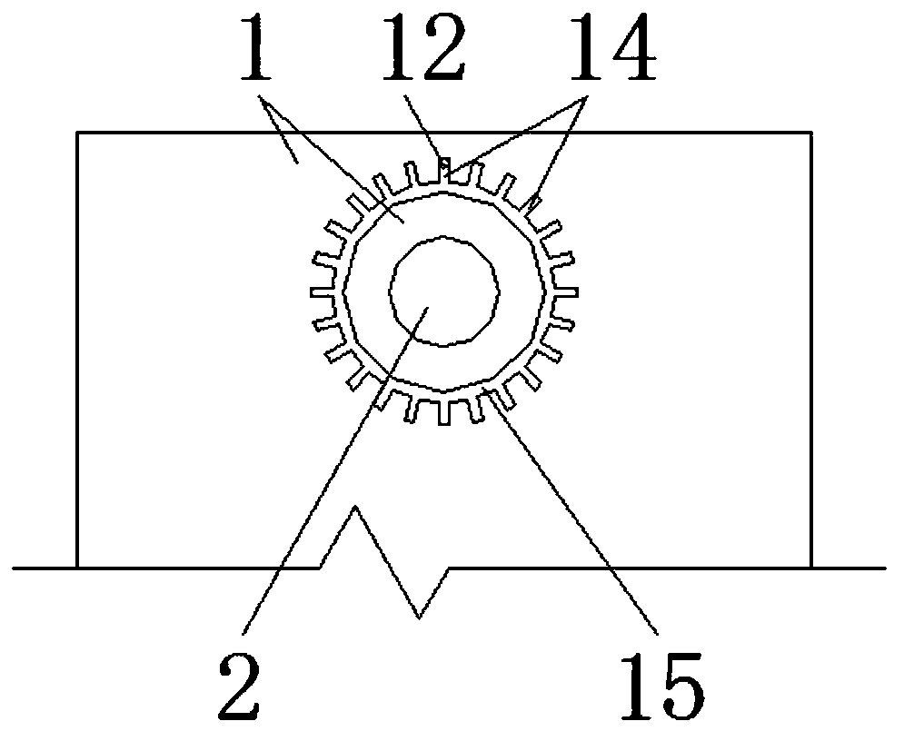
[0021] see Figure 1-4 , the present invention provides a technical solution: a rotation control mechanism of a rotary welding device, including a support frame 1, a welding cabinet 2, a rotating shaft 3 and a clamping platform 5, a welding cabinet 2 is fixedly installed on the left side of the support frame 1, and supports The top bearing of the frame 1 is connected with a rotating shaft 3, the outer surface of the rotating shaft 3 is welded with a fixed plat...


PUM


Abstract

The invention discloses a rotation control mechanism of a rotary welding device. The rotation control mechanism of the rotary welding device includes a support frame, a welding machine case, a rotating shaft and a clamping platform; the left side of the support frame is fixedly installed with the welding machine case; a top bearing of the support frame is connected with the rotating shaft; a fixing plate is welded and installed on the outer surface of the rotating shaft, and the clamping platform is fixedly installed on the top surface of the fixing plate; the right end of the rotating shaft is connected to the center of a turntable, and the interior of the turntable is provided with a receiving groove; a connecting spring is installed in the receiving groove; and the top end of the connecting spring is fixedly connected to a connecting block. According to the rotation control mechanism of the rotary welding device, the staff can pull a connecting shaft to make the connecting shaft drive the connecting block for a contraction operation, so that the follow-up staff can turn the connecting shaft to make the connecting shaft drive the turntable for a rotation operation, which is convenient for the operation and use of the staff, and meanwhile improves the comfort during operation.

Description

technical field [0001] The invention relates to the technical field of welding devices, in particular to a rotation control mechanism of a rotary welding device. Background technique [0002] The welding device refers to the equipment for welding work, so that the two objects can be effectively fixed through the welding device, and the welding device can be operated cooperatively through different auxiliary equipment, including the rotation control mechanism. [0003] At present, the rotation control mechanism of the rotary welding device that is common on the market, in the process of using it, when the staff manually rotates it, the operation method is not convenient and comfortable enough, which affects the staff's understanding of the rotation control mechanism. Using work, aiming at the above problems, innovative design is carried out on the basis of the rotation control mechanism of the original rotary welding device. Contents of the invention [0004] The purpose o...

Claims


Application Information

Patent Timeline
Patent Type & Authority Applications(China)
IPC IPC(8): B23K37/047B23K37/04
CPCB23K37/04B23K37/0461B23K37/047
Inventor 张家愉
Owner HUANGSHI HENGSHENG TECH CO LTD
Learn More