Floor embossing device for road construction

A road construction and floor embossing technology, which is applied in the field of floor embossing devices for road construction, can solve problems such as high labor intensity, reduced embossing efficiency, and poor embossing effect, so as to reduce labor intensity and improve embossing efficiency Effect

Active Publication Date: 2021-10-26
临清市宏顺国际贸易有限公司
View PDF7 Cites 0 Cited by
  • Summary
  • Abstract
  • Description
  • Claims
  • Application Information

AI Technical Summary

Problems solved by technology

[0003] In order to make the floor show colorful patterns and make the floor more wear-resistant, pressure-resistant, and non-slip, it is common to emboss the cast-in-place concrete floor. When embossing the concrete floor, when the embossing roller is hand-held for embossing, the embossing roller needs to be manually pushed to the right. When the embossing roller moves to the edge of the floor, the embossing roller needs to be lifted manually, and then Finally, move the embossing roller, then put down the embossing roller and pull the embossing roller to the left to emboss the floor, so workers need to hold the embossing roller for a long time to emboss, the labor intensity is high, and it is easy to cause arm pain. In turn, the embossing efficiency is reduced. If the worker accidentally releases the embossing roller, it will easily lead to poor embossing effect.

Method used


Image

  • Floor embossing device for road construction
  • Floor embossing device for road construction
  • Floor embossing device for road construction

Examples


Embodiment 1

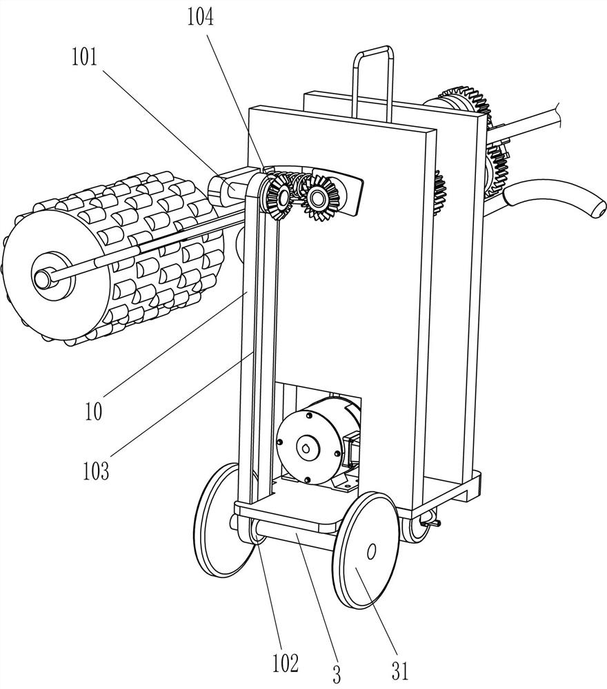
[0027] A floor embossing device for road construction, such as figure 1 , figure 2 , Figure 4 and Figure 5 As shown, it includes base 1, universal wheel 2, connecting shaft 3, traveling wheel 31, support plate 4, driving mechanism 5, moving mechanism 6, moving rod 7 and pressure roller 8, and the bottom front side of base 1 is connected with ten thousand To the wheel 2, the bottom rear side of the base 1 is rotatably connected to the connecting shaft 3, the left and right ends of the connecting shaft 3 are connected to the walking wheels 31, the front and rear sides of the top of the base 1 are connected to the support plate 4, and the two support plates A driving mechanism 5 is installed on the top of the base 1 between 4, and a moving mechanism 6 is installed on the left side of the upper part of the front support plate 4. The driving mechanism 5 is connected to the moving mechanism 6, and a moving rod 7 is placed on the moving part of the moving mechanism 6. , the rig...

Embodiment 2

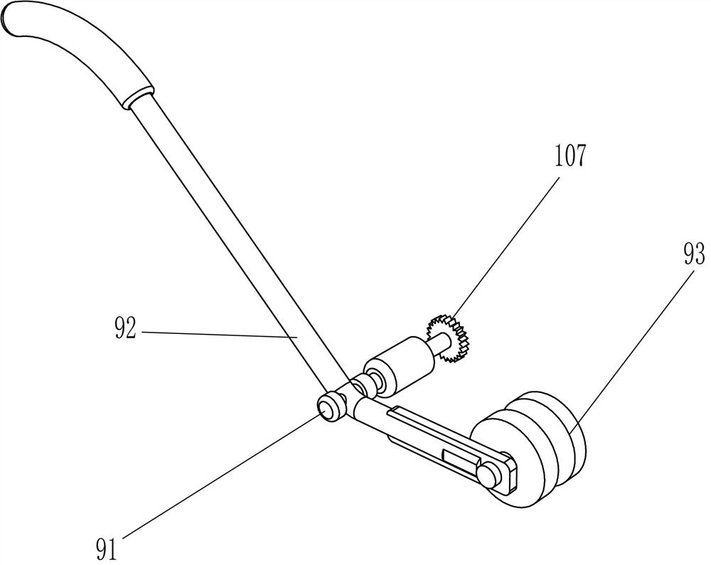
[0032] On the basis of Example 1, such as Figure 1-2 As shown, it also includes a tilting device 9, the tilting device 9 includes a fourth rotating shaft 91, a swing lever 92 and a support wheel 93, and the lower right part of the front side support plate 4 is rotatably connected with a fourth rotating shaft 91, and the fourth rotating shaft 91 runs through the front side support plate 4, and the front part of the fourth rotating shaft 91 is connected with a swing bar 92, and the rear side right part of the swing bar 92 is fixedly connected with a support wheel 93, and the support wheel 93 contacts with the moving bar 7.

[0033] Manually press the left side of the swing lever 92 downward, the right side of the swing lever 92 swings upwards accordingly, the fourth rotating shaft 91 rotates counterclockwise thereupon, the right side of the swing lever 92 swings upwards and pushes the moving lever 7 to move upwards, thereby enabling Lift the pressure roller 8. When the moving ...

Embodiment 3

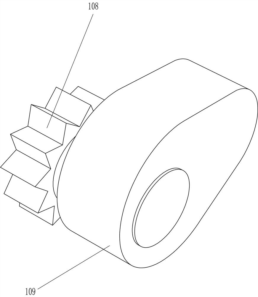
[0035] On the basis of Example 2, such as Figure 4-7 As shown, a linkage assembly 10 is also included, and the linkage assembly 10 includes a fifth rotating shaft 101, a second pulley 102, a second flat belt 103, a first bevel gear 104, a second bevel gear 105, an L-shaped rod 106, a large gear 107, pinion 108, cam 109, the rear side right side of rear side supporting plate 4 is connected with the fifth rotating shaft 101 in a rotary type, the fifth rotating shaft 101 and the connecting shaft 3 are all connected with the second pulley 102, two second pulleys The second flat belt 103 is connected between 102, the left end of the fifth rotating shaft 101 is connected with the first bevel gear 104, the rear end of the first rotating shaft 55 is connected with the second bevel gear 105, the second bevel gear 105 and the first bevel gear 104 meshing, the middle part of the right side of the connecting plate 52 is connected with an L-shaped bar 106, the rear end of the fourth rotat...


PUM


Abstract

The invention relates to an embossing device for road construction, in particular to a floor embossing device for road construction. The technical problem to be solved by the present invention is how to provide a floor embossing device for road construction that can reduce labor intensity and improve embossing efficiency. In order to solve the above technical problems, the present invention provides such a floor embossing device for road construction, comprising: a base, one end of which is connected with a universal wheel, and one end of the base close to the universal wheel is rotatably connected with a connecting shaft, the connecting shaft There are walking wheels connected to the top, and supporting plates are connected to both sides of the other end of the base; a driving mechanism is installed on the other end of the base close to the supporting plate; a moving mechanism is installed on one side of the supporting plate, and the driving mechanism and the moving Mechanism transmission connection. The present invention can emboss the cast-in-place concrete floor by moving and rotating the pressure roller to the right and left, thus eliminating the need for manual hand-held embossing rollers for a long time for embossing.

Description

technical field [0001] The invention relates to an embossing device for road construction, in particular to a floor embossing device for road construction. Background technique [0002] The floor can be divided into broad sense and narrow sense. In the broad sense, the floor refers to the collective name of various grounds. In the narrow sense, the floor refers to the use of some tools and materials to make the ground show a good decorative effect. [0003] In order to make the floor show colorful patterns and make the floor more wear-resistant, pressure-resistant, and non-slip, it is common to emboss the cast-in-place concrete floor. When embossing the concrete floor, when the embossing roller is hand-held for embossing, the embossing roller needs to be manually pushed to the right. When the embossing roller moves to the edge of the floor, the embossing roller needs to be lifted manually, and then Finally, move the embossing roller, then put down the embossing roller and p...

Claims


Application Information

Patent Timeline
Patent Type & Authority Patents(China)
IPC IPC(8): E01C19/43
CPCE01C19/43
Inventor 肖承磊
Owner 临清市宏顺国际贸易有限公司
Why Eureka
Try Eureka