A medical anesthesia assisting device

An auxiliary device and placement slot technology, which is applied in hypnotic devices, anesthesia appliances, medical science and other directions, can solve the problems of inability to locate the location of anesthesia injection, affect the treatment effect, and poor disinfection effect of anesthesia instruments, and achieve good sterilization and disinfection effects. Easy to operate anesthesia, good disinfection effect

Active Publication Date: 2022-05-13
山东省曹县第二人民医院
View PDF0 Cites 0 Cited by
  • Summary
  • Abstract
  • Description
  • Claims
  • Application Information

AI Technical Summary

Problems solved by technology

[0004] When performing an operation on a patient, it is generally necessary to anesthetize the patient first, and an anesthesia assisting device is generally required for anesthesia. However, most of the anesthesia assisting devices currently on the market are relatively simple and have a single function. The anesthesia operation takes a long time, and the doctor’s arm is kept in one position for a long time, which can easily cause arm soreness. The doctor’s arm muscle tension increases, which reduces the stability of the anesthesia solution and directly affects the treatment effect. At the same time, the existing anesthesia assistance The device cannot locate the anesthesia injection position, cannot ensure its precise injection at the designated anesthesia position, and it is difficult to achieve the ideal work effect, so that the overall use effect and work performance are relatively average, and the anesthesia equipment needs to be sterilized before use. Some anesthesia assisting devices have poor disinfection effect on anesthesia equipment and are inconvenient to use

Method used


Image

  • A medical anesthesia assisting device
  • A medical anesthesia assisting device
  • A medical anesthesia assisting device

Examples


Embodiment 1

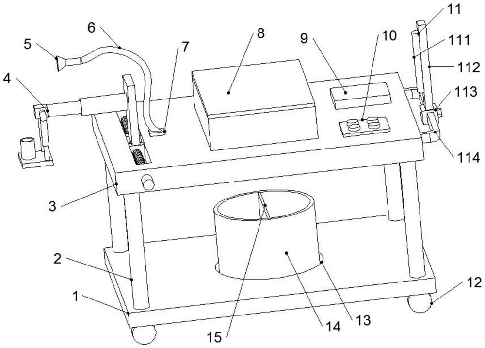
[0026] see Figure 1-3 , the present invention provides a technical solution for a medical anesthesia assisting device: including a base 1, universal wheels 12 are provided at the four corners of the bottom of the base 1 (the universal wheels are provided with self-locking devices, which belong to the prior art, and no further details will be made here. Explanation), easy to move, the top center of the base 1 is provided with a placement groove 13, and a garbage can 14 is placed in the placement groove 13 to prevent the garbage can 14 from toppling over, and the four corners of the top of the base 1 are fixedly connected with support rods 2 The top is fixedly connected with a top plate 3, and the support rod 2 can support the top plate 3. There is a chute 17 on the left side of the top of the top plate 3, and a screw rod 18 is arranged in the chute 17. The inner end of the screw rod 18 passes through the bearing and the sliding The inner wall of the groove 17 is rotationally c...

Embodiment 2

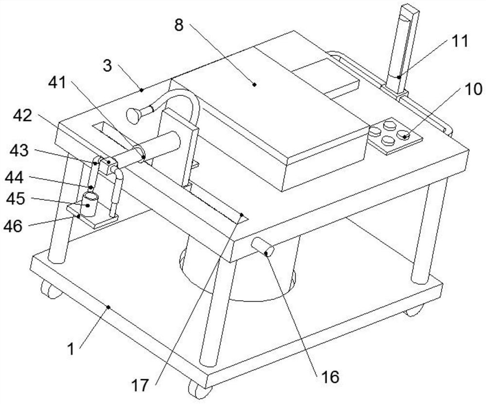
[0028] see Figure 1-4 , the present invention provides a technical solution of a medical anesthesia auxiliary device: the present invention provides a technical solution of a medical anesthesia auxiliary device: comprising a base 1, universal wheels 12 are provided at the four corners of the bottom of the base 1 (self-locking wheels are provided on the universal wheels device, which belongs to the prior art, and will not be further elaborated here), is convenient to move, and the center of the top of the base 1 is provided with a placement groove 13, and a garbage can 14 is placed in the placement groove 13 to prevent the garbage can 14 from toppling over, and the four corners of the top of the base 1 The top of the support rod 2 is fixedly connected with the top plate 3, and the support rod 2 can support the top plate 3. There is a chute 17 on the left side of the top of the top plate 3, and the chute 17 is provided with a wire Rod 18, the inner end of screw mandrel 18 is ro...

Embodiment 3

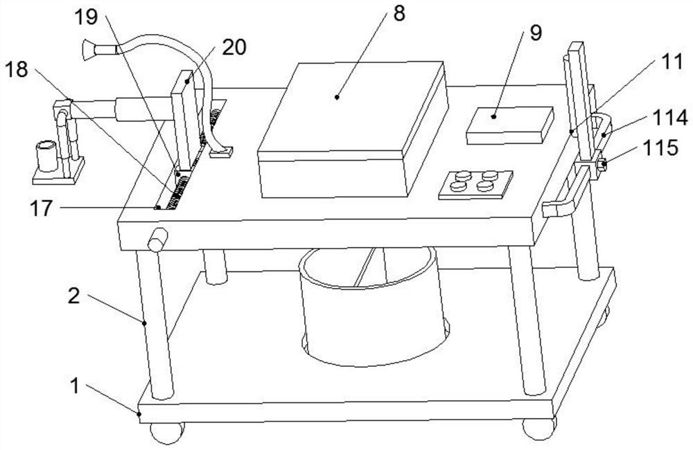
[0031] see Figure 1-4 , the present invention provides a technical solution for a medical anesthesia assisting device: including a base 1, universal wheels 12 are provided at the four corners of the bottom of the base 1 (the universal wheels are provided with self-locking devices, which belong to the prior art, and no further details will be made here. Explanation), easy to move, the top center of the base 1 is provided with a placement groove 13, and a garbage can 14 is placed in the placement groove 13 to prevent the garbage can 14 from toppling over, and the four corners of the top of the base 1 are fixedly connected with support rods 2 The top is fixedly connected with a top plate 3, and the support rod 2 can support the top plate 3. There is a chute 17 on the left side of the top of the top plate 3, and a screw rod 18 is arranged in the chute 17. The inner end of the screw rod 18 passes through the bearing and the sliding The inner wall of the groove 17 is rotationally c...


PUM


Abstract

The invention discloses a medical anesthesia auxiliary device, which comprises a base, a placement groove is opened on the top of the base, a garbage can is placed in the placement groove, a support rod is connected to the top of the base, a top plate is connected to the support rod, and a chute is opened on the left side of the top of the top plate , There is a screw rod in the chute, two groups of sliders are screwed on the screw rod, the top of the slider is connected with a connecting plate, the connecting plate is connected with a positioning auxiliary component, the top of the top plate is equipped with a lamp holder, and the lamp holder passes through the gooseneck It is connected with a lighting lamp, an instrument box is set on the top plate, a storage battery and a control panel are set on the top right side of the top plate, and an adjustable disinfection component is set on the right side of the top plate; the invention can adjust the position of the auxiliary positioning component according to the needs of the operation, and the positioning effect is good , at the same time, the position and angle of the lighting can be adjusted through the gooseneck. The lighting effect is good, which is convenient for medical staff to perform anesthesia operations. The instruments needed for anesthesia can be placed in the instrument box for easy use. The adjustable disinfection components Sterilize the instruments in the instrument case.

Description

technical field [0001] The invention relates to the technical field of anesthesia assisting devices, in particular to a medical anesthesia assisting device. Background technique [0002] The meaning of anesthesia is to use drugs or other methods to temporarily deprive the patient of the whole or part of the sensation, so as to achieve the purpose of painless surgical treatment. Anesthesiology is a science that uses basic theories, clinical knowledge and techniques related to anesthesia to eliminate surgical pain, ensure patient safety, and create favorable conditions for surgery. [0003] Now, anesthesiology has become a specialized independent discipline in clinical medicine, mainly including clinical anesthesiology, emergency resuscitation medicine, intensive care monitoring therapy, pain diagnosis and treatment, and other related medicine and its mechanism research. Comprehensive discipline of pain, emergency resuscitation and critical care medicine. Among them, clinica...

Claims


Application Information

Patent Timeline
Patent Type & Authority Patents(China)
IPC IPC(8): A61B50/13A61B50/30A61M5/42A61M19/00A61L2/10
CPCA61B50/13A61B50/30A61M5/427A61M19/00A61L2/10A61M2205/587A61L2202/24
Inventor 石长武徐冬梅
Owner 山东省曹县第二人民医院
Why Eureka
Try Eureka