
Electric wire buckle convenient to disassemble

A buckle and wire technology, applied in the direction of electrical components, etc., can solve the problems of increasing safety hazards and operation difficulty, time-consuming and labor-consuming, cumbersome process, etc., and achieve the effect of easy replacement, low operation difficulty and simple operation

Inactive Publication Date: 2020-08-07
江苏中顺电气有限公司
View PDF7 Cites 0 Cited by
  • Summary
  • Abstract
  • Description
  • Claims
  • Application Information

AI Technical Summary

Problems solved by technology

[0002] In the prior art, the wire buckle usually includes an upper buckle, a lower buckle, and a locking nut. The screw rod on the upper buckle is inserted into the lower buckle, and the wire is positioned on the upper buckle and the lower buckle at the same time. In the buckle collar formed between the buckle parts, the locking operation of the wire is realized through the lock nut. The defect and deficiency of this operation method is that each time in the process of disassembly, the lock nut needs to be After unscrewing along the axial direction of the screw on the upper buckle, separate the upper buckle and the lower buckle, and then take out the buckle collar formed between the upper buckle and the lower buckle The wires in the process are cumbersome, time-consuming and labor-intensive, and most of the wires are located at high places. Manually located at high places increases safety hazards and operational difficulties in the process of rotating the lock nut.

Method used


Image

  • Electric wire buckle convenient to disassemble
  • Electric wire buckle convenient to disassemble
  • Electric wire buckle convenient to disassemble

Examples


Embodiment Construction

[0027] The present invention is described in further detail now in conjunction with accompanying drawing. These drawings are all simplified schematic diagrams, which only illustrate the basic structure of the present invention in a schematic manner, so they only show the configurations related to the present invention.

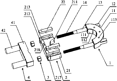
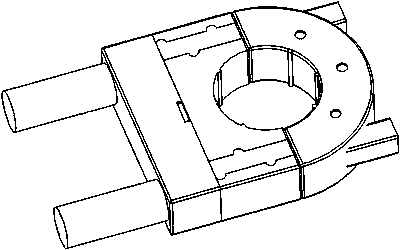
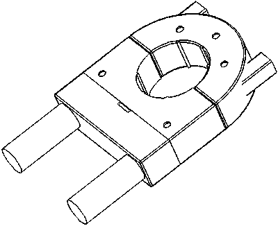
[0028] Such as Figure 1-7 As shown, a wire clip that is easy to disassemble includes an upper clip 1, a lower clip 2, a lock nut 3, and a clip sleeve 4; wherein, the upper clip body 11 of the upper clip 1 An upper snap ring 111 is arranged at the lower center of the lower snap part 2, and a lower snap snap ring 211 is arranged at the upper center of the lower snap body 21 of the lower snap part 2, and the upper snap snap ring 111 and the lower snap snap ring 211 are spliced ​​together. A buckle collar for accommodating electric wires is formed, the upper sides of the upper buckle body 11 of the upper buckle part 1 protrude from the buckle clamping end 12, an...


PUM


Abstract

The invention relates to an electric wire buckle convenient to disassemble, which is characterized by comprising an upper buckle piece, a lower buckle piece, a locking nut and a buckle sleeve body, ascrew rod insulator and a screw rod extend out of two sides below an upper buckle body of the upper buckle piece; the diameter of the screw insulator is greater than that of the screw; the screw insulator extends into a positioning hole of the lower fastener; after the screw rod penetrates through the positioning hole of the lower buckling piece, the upper buckling piece and the lower buckling piece are mounted and locked through the locking nut; and the buckle sleeve body is installed on the outer side of the lower buckle piece and used for wrapping the screw and the locking nut. The lower buckle piece comprises a lower buckle body; a mounting through groove is formed in one side of the positioning hole in the lower buckle body, the shape of a lower buckle plug is matched with that of the mounting through groove, the lower buckle plug and the lower buckle body can be mounted and combined to form the positioning hole, the width of the mounting through groove is smaller than that of the positioning hole, and the mounting through groove can allow a screw to pass but cannot allow a screw insulator to pass.

Description

technical field [0001] The invention relates to a wire buckle, in particular to a wire buckle which is easy to disassemble. Background technique [0002] In the prior art, the wire buckle usually includes an upper buckle, a lower buckle, and a locking nut. The screw rod on the upper buckle is inserted into the lower buckle, and the wire is positioned on the upper buckle and the lower buckle at the same time. In the buckle collar formed between the buckle parts, the locking operation of the wire is realized through the lock nut. The defect and deficiency of this operation method is that each time in the process of disassembly, the lock nut needs to be After unscrewing along the axial direction of the screw on the upper buckle, separate the upper buckle and the lower buckle, and then take out the buckle collar formed between the upper buckle and the lower buckle The wires in the process are cumbersome, time-consuming and labor-intensive, and most of the wires are located at h...

Claims


Application Information

Patent Timeline
Patent Type & Authority Applications(China)
IPC IPC(8): H02G3/02
CPCH02G3/02
Inventor 刘洋
Owner 江苏中顺电气有限公司
Learn More