
User-defined partition dotting counter

A counter and self-defined technology, applied to instruments, metronomes, teaching models, etc., can solve problems such as frequency drift, large frequency converter components, and influence on speed regulation accuracy, and achieve the effect of short friction

Active Publication Date: 2020-08-07
李建勋
View PDF14 Cites 0 Cited by
  • Summary
  • Abstract
  • Description
  • Claims
  • Application Information

AI Technical Summary

Problems solved by technology

[0003] In the existing technology, electromagnetic counters and electric sparks are commonly used. These two generally do not have the function of frequency conversion. If the dot frequency needs to be changed, it needs to be changed by changing the frequency of the input current. However, not only the frequency converter components are large, It is not conducive to integration in a compact dot counter. Moreover, the frequency of the frequency converter is not only fluctuated by its own reasons, but also by the interference of the surrounding electromagnetic field, resulting in frequency drift and speed regulation accuracy.
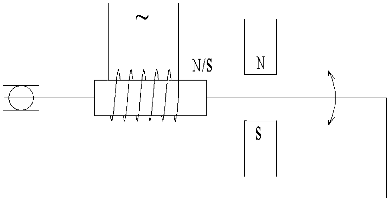
[0004] In addition, the contact between the striker of the electromagnetic dot counter and the paper tape is carried out by electromagnetic attraction, such as figure 1 As shown, it is the structure of the basic electromagnetic dotting counter. The vibration of the striker is roughly sinusoidal. The bottom of the striker cannot rebound during the contact period with the paper tape. That is to say, the friction between the striker and the paper tape is relatively large, which will affect the paper. belt movement

Method used


Image

  • User-defined partition dotting counter
  • User-defined partition dotting counter
  • User-defined partition dotting counter

Examples


Embodiment Construction

[0031] The following will clearly and completely describe the technical solutions in the embodiments of the present invention with reference to the accompanying drawings in the embodiments of the present invention. Obviously, the described embodiments are only some, not all, embodiments of the present invention. Based on the embodiments of the present invention, all other embodiments obtained by persons of ordinary skill in the art without making creative efforts belong to the protection scope of the present invention.

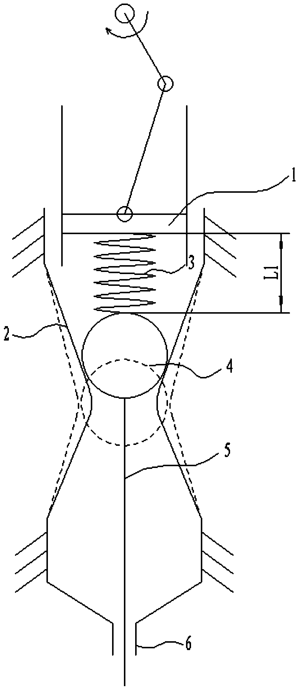
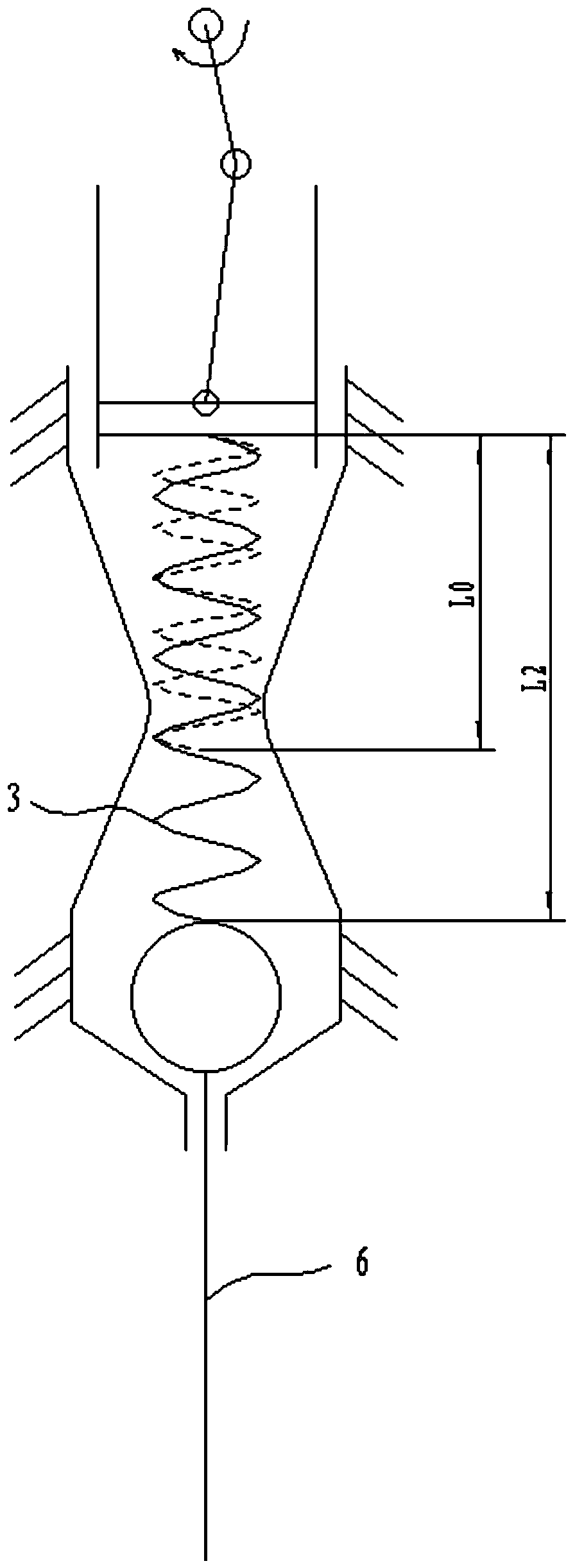
[0032] Such as figure 2 , 3 As shown, a self-defined partition counter includes a slider 1, a reed 2, a spring 3, a ball spacer 4 and a striker 5. The slider 1 is installed in a vertical guide groove and the back is driven to move linearly back and forth The lower surface of the slide block 1 is connected to one end of the spring 3, and the other end of the spring 3 is connected to the ball 4, and the reed 2 is left and right symmetrical and forms an elastic m...


PUM


Abstract

The invention discloses a user-defined partition dotting counter, which comprises a sliding block, reeds, a spring, a separation ball and a firing pin, wherein the sliding block is installed in a vertical guide groove, the back surface of the sliding block is driven to move linearly in a reciprocating mode, the lower surface of the sliding block is connected with one end of the spring, the other end of the spring is connected with the separation ball, the reeds are bilaterally symmetrical and form elastic gaps in the two sides of the separation ball, and the separation ball faces towards to install the firing pin. The reciprocating lifting motion of the sliding block can be completed through a basic structure of an electromagnetic dotting counter in the prior art, a rod head at one end ofan electromagnet is connected to the upper surface of the sliding block, the electromagnet generates an alternating magnetic pole at the end of the electromagnet under alternating current, and the electromagnet is attracted by a fixed permanent magnet to vibrate up and down to complete up-down reciprocating motion. The bottom ends of the reeds extend downwards and are connected to form an annularguide hole, and the firing pin penetrates through the guide hole downwards.

Description

technical field [0001] The invention relates to the field of motion analysis equipment, in particular to a self-defined partition dotting counter. Background technique [0002] A dot counter, also known as a dot timer, is a device that produces small dots on a paper tape at a certain time interval, and is often used in physical experiments to analyze the state of motion of objects. The object drags a paper tape to move, and the dots printed on the paper tape show the position of the object at different times. [0003] In the existing technology, electromagnetic counters and electric sparks are commonly used. These two generally do not have the function of frequency conversion. If the dot frequency needs to be changed, it needs to be changed by changing the frequency of the input current. However, not only the frequency converter components are large, It is not conducive to integration in a compact dot counter. Moreover, the frequency of the frequency converter is not only f...

Claims


Application Information

Patent Timeline
Patent Type & Authority Applications(China)
IPC IPC(8): G09B23/06G04F5/02
CPCG04F5/02G09B23/06
Inventor 王泽斌
Owner 李建勋
Learn More