
Auxiliary displacement equipment

A kind of equipment and displacement technology, which is applied to conveyor control devices, conveyor objects, transportation and packaging, etc., can solve the problems of insufficient adjustment, inability to accurately adjust the position of goods, and falling goods, etc., to prevent excessive adjustment and adjustment. Not in place

Inactive Publication Date: 2020-08-07
深圳成丰商企服务有限公司
View PDF5 Cites 0 Cited by
  • Summary
  • Abstract
  • Description
  • Claims
  • Application Information

AI Technical Summary

Problems solved by technology

However, the use of the deflection plate cannot accurately adjust the position of the goods. If the goods are parallel or large, it is easy to cause the goods to fall from the conveying mechanism, resulting in damaged parts. If the goods are small, it will cause incorrect adjustment. in place

Method used


Image

  • Auxiliary displacement equipment
  • Auxiliary displacement equipment
  • Auxiliary displacement equipment

Examples


Embodiment Construction

[0025] The following will clearly and completely describe the technical solutions in the embodiments of the present invention with reference to the accompanying drawings in the embodiments of the present invention. Obviously, the described embodiments are only some, not all, embodiments of the present invention. All other embodiments obtained by persons of ordinary skill in the art based on the embodiments of the present invention belong to the protection scope of the present invention.

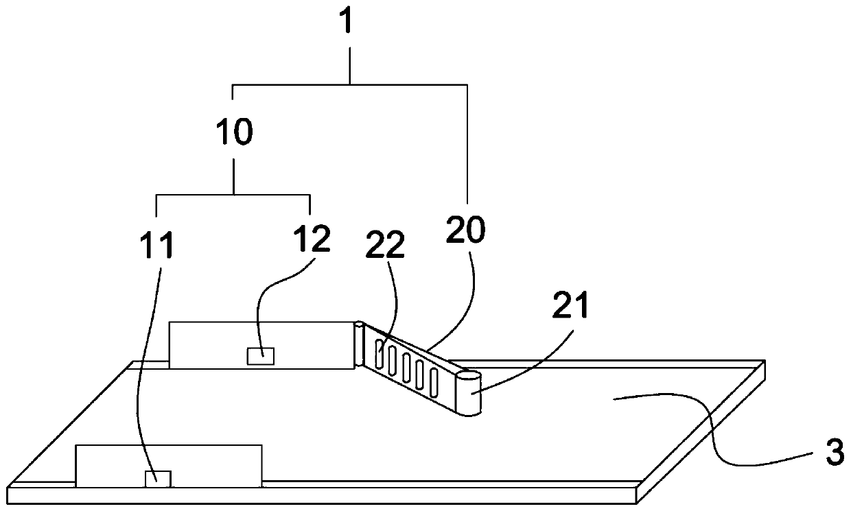
[0026] figure 1 It is a schematic structural diagram of the auxiliary displacement device described in the embodiment of the present invention.

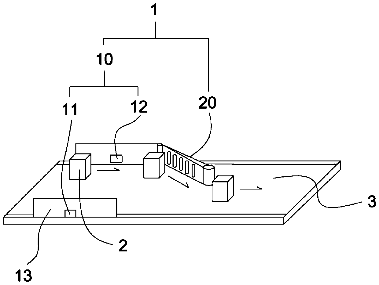
[0027] figure 2 It is a schematic diagram of the operation of the auxiliary displacement device described in the embodiment of the present invention.

[0028] Such as figure 1 , figure 2 As shown, an auxiliary displacement device 1 according to an embodiment of the present invention includes: a positioning device 10, the positioning device 10 ...


PUM


Abstract

The invention discloses auxiliary displacement equipment, comprising a positioning device, a mechanical swing arm and a data processing device. The positioning device comprises distance measuring devices oppositely arranged on the two sides of a conveying mechanism, wherein the distance measuring devices are used for obtaining distance data when an object passes through; the mechanical swing arm adjusts a transverse position of the object on the conveying mechanism through self-swinging; and the data processing device calculates the swinging angle of the mechanical swing arm according to the data obtained through the positioning device to make the object reach a predetermined position on the conveying mechanism. The auxiliary displacement equipment has the beneficial effects that positionsof goods are determined through the positioning device, adjusting positions of the goods are determined accordingly, and the situations of excessive adjustment and poor adjustment are prevented.

Description

technical field [0001] The invention relates to the technical field of cargo transportation, in particular to an auxiliary displacement device. Background technique [0002] In the field of logistics, it is often necessary to use large-scale conveying mechanisms to transport goods to various stations. The staff at each station usually receive the goods from one side of the conveying mechanism. If the position of the goods on the conveying mechanism is far away from the staff, it will be very inconvenient to receive the goods. In order to solve this problem, in the prior art, a deflection plate is used to deflect the goods to one side of the conveying mechanism, which is convenient for the staff to receive the goods. However, the use of the deflection plate cannot accurately adjust the position of the goods. If the goods are parallel or large, it is easy to cause the goods to fall from the conveying mechanism, resulting in damaged parts. If the goods are small, it will cause...

Claims


Application Information

Patent Timeline
Patent Type & Authority Applications(China)
IPC IPC(8): B65G47/22B65G43/08
CPCB65G43/08B65G47/22
Inventor 张志勇
Owner 深圳成丰商企服务有限公司
Learn More