
Key biting recognition device

A technology for identifying devices and keys, which is applied to measuring devices, electrical devices, electromagnetic measuring devices, etc., can solve the problems of increasing the manufacturing cost of locks, unable to guarantee the accuracy of the key head tooth pattern, complex tooth pattern structure, etc.

Active Publication Date: 2020-07-31
ZHUHAI UNITECH POWER TECH CO LTD
View PDF4 Cites 0 Cited by
  • Summary
  • Abstract
  • Description
  • Claims
  • Application Information

AI Technical Summary

Problems solved by technology

[0002] At present, most of the keys are processed by milling technology, and then, the tooth pattern series of the key head is obtained through manual measurement, and the lock cylinder production equipment will manufacture the corresponding lock cylinder according to the tooth pattern series of the key head, but due to the The flower structure is complex and delicate, so that the manual measurement method cannot guarantee the accuracy of the tooth flower series of the key head, and it does not match the manufactured lock cylinder, thereby increasing the production cost of the lock

Method used


Image

  • Key biting recognition device
  • Key biting recognition device
  • Key biting recognition device

Examples


Embodiment Construction

[0059] To make the purpose, technical solutions, and advantages of the embodiments of the present application clearer, the technical solutions in the embodiments of the present application will be described below in conjunction with the drawings in the embodiments of the present application. In addition, it should be noted that similar reference numerals and letters indicate similar items in the following figures. Therefore, once an item is defined in one figure, it does not need to be further defined and defined in subsequent figures. Explanation.

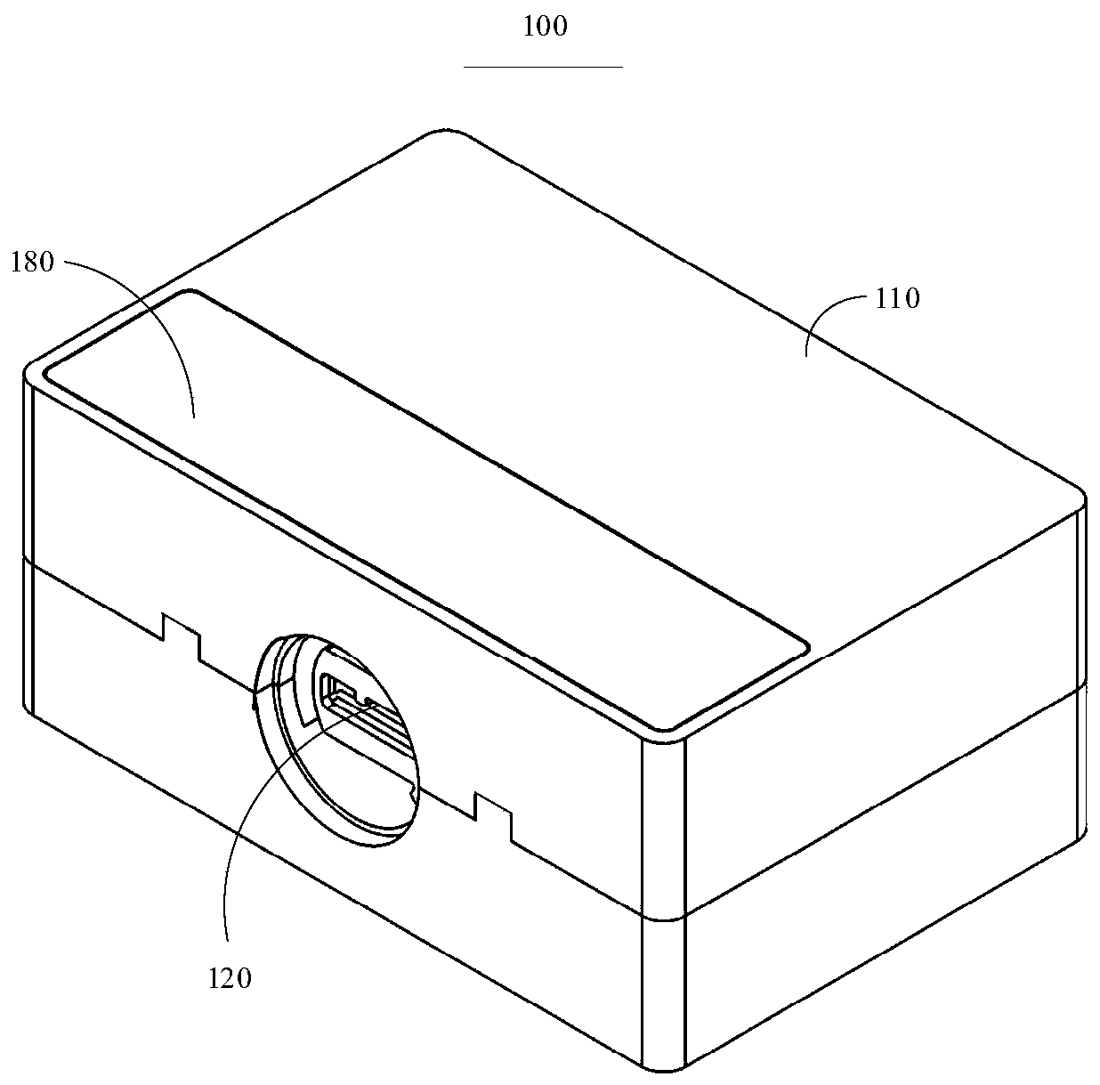
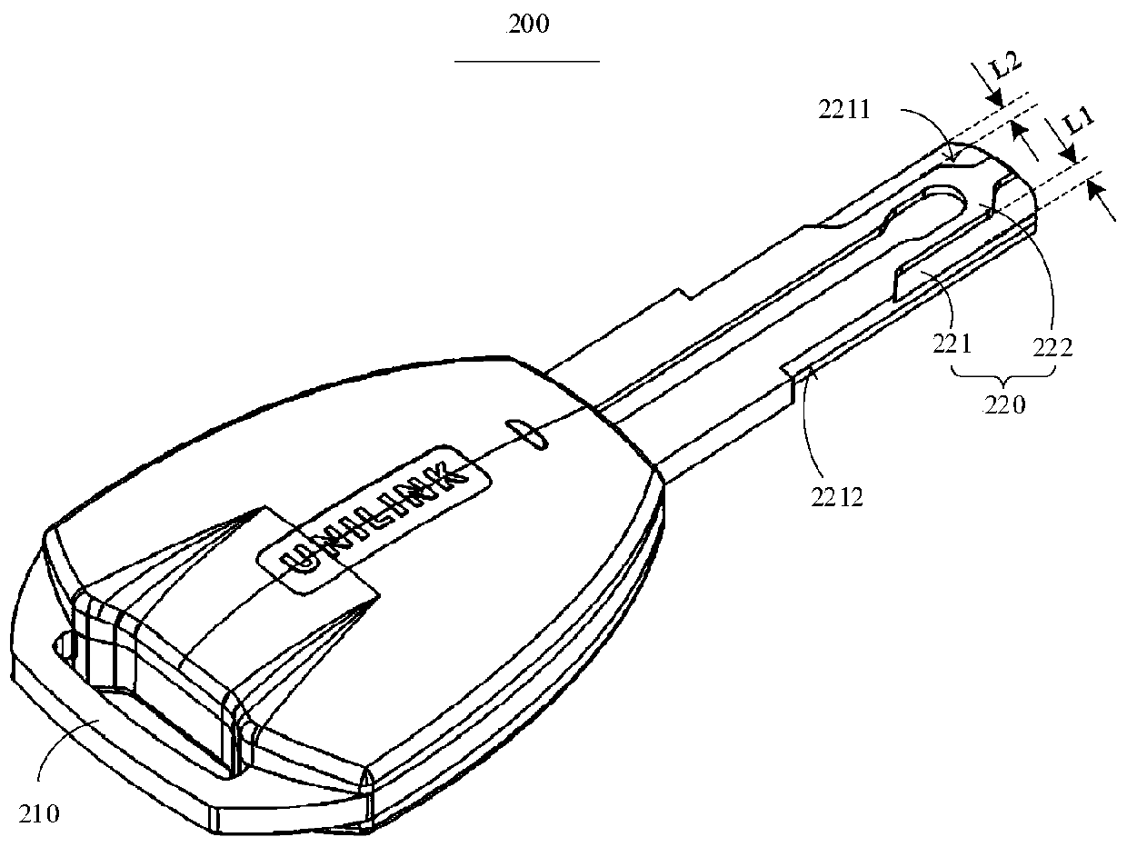
[0060] See figure 1 with figure 2 , The embodiment of the present application provides a key tooth flower recognition device 100, which is used to identify or assist in identifying the key 200 tooth flower series. In the embodiment of the present application, the key 200 includes a key handle 210 and a key head 220, the key head 220 is disposed on the key handle 210, and the key head 220 includes a key head body 221, and the key hea...


PUM


Abstract

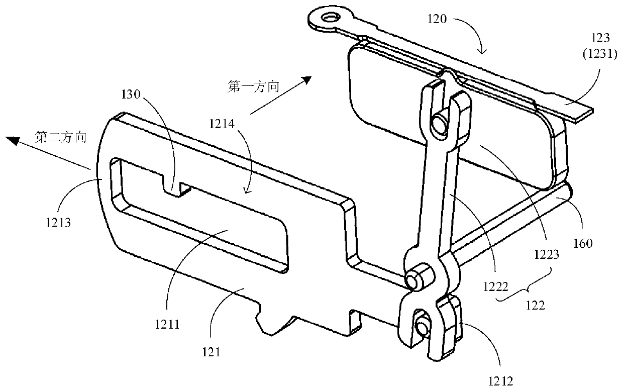
The invention relates to a key biting recognition device. The device comprises a shell and at least one set of recognition assembly arranged in the shell, the recognition assembly comprises a blade, asliding mechanism, a variable resistance device and a recognition circuit, and the sliding mechanism is made of a conductor material. A key hole and a stop block are arranged on the blade, the key hole is used for allowing a key bit to be inserted, and the stop block is used for controlling the blade to move under the extrusion effect of a biting structure when the key bit is inserted into the key hole. One end of the sliding mechanism is connected with the blade, and the other end of the sliding mechanism is arranged on the variable resistance device and can slide relative to the variable resistance device. The first end of the recognition circuit is connected to the sliding mechanism, the second end of the recognition circuit is connected to one end of the variable resistance device, and the recognition circuit is used for obtaining electrical parameters representing the actual resistance value of the variable resistance device connected to the recognition circuit so as to calculatethe biting stage number of the key bit through the electrical parameters. According to the key biting recognition device provided by the embodiment of the invention, the accuracy of the key bit biting stage number can be ensured.

Description

Technical field [0001] This application relates to the field of production and manufacturing of locks, in particular to a key tooth flick recognition device. Background technique [0002] At present, most of the keys are processed by milling technology. Then, the tooth pattern of the key head is obtained by manual measurement. The lock core production equipment will manufacture the corresponding lock cylinder according to the tooth pattern of the key head. The structure of the flower is complicated and exquisite, so that the manual measurement method cannot guarantee the accuracy of the key head tooth flower series, and it does not match the manufactured lock core, thereby increasing the manufacturing cost of the lock. Summary of the invention [0003] The purpose of the embodiments of the present application is to provide a key flick recognition device to solve the above-mentioned problems. [0004] The key tooth pattern recognition device provided by the embodiment of the present...

Claims


Application Information

Patent Timeline
IPC IPC(8): G01B7/28G01B7/00G01M13/00
CPCG01B7/28G01B7/00G01M13/00
Inventor 李保福李启平杨绍华陈华
Owner ZHUHAI UNITECH POWER TECH CO LTD
Learn More