Elastic pressing type hot-line work insulating lock rod

A live operation, elastic pressing technology, applied in the direction of overhead lines/cable equipment, etc., can solve the problems of difficult adjustment of the length of the insulating lock rod, hidden dangers of accident safety, complicated use, etc., so as to reduce physical energy consumption, lower the use threshold, and open and close freely. Effect

Pending Publication Date: 2020-07-28
国网河南省电力公司辉县市供电公司 +2
View PDF1 Cites 2 Cited by
  • Summary
  • Abstract
  • Description
  • Claims
  • Application Information

AI Technical Summary

Problems solved by technology

[0002] The insulating locking rod is one of the necessary tools in the live work of 10kV distribution lines. The existing insulating locking rod is a rotary movable head insulating locking rod, which is extremely inconvenient to operate in specific work, often resulting in the locking of the lock and the loosening of the wire Phenomenon, it is easy to cause accident safety hazards, and the operation intensity is high, which is extremely inconvenient
[0003] The Chinese patent with the publication number CN208190117U discloses an insulating lock bar for live work, including a fixing seat, a cavity is opened in the fixing seat, a clamping plate is arranged in the cavity, and one side wall of the clamping plate is A threaded rod is fixedly connected, and the end of the threaded rod away from the clamping plate runs through the side wall of the fixing seat and is fixedly connected with a splint. The threaded rod is threaded with a threaded plate, and the threaded plate is away from the side wall of the fixing seat. A connecting rod is fixedly connected, and one end of the connecting rod away from the threaded plate is fixedly connected with a fixed plate, and the other end of the limiting rod penetrates through the threaded plate and is fixedly connected with a limiting block. By setting a rotating rod and a locking block, it can The locking block is clamped in the locking groove on the rotating rod, thereby adjusting the length of the insulating locking rod, which can mainly solve the problem that the length of the existing insulating locking rod is not easy to adjust, but its use is cumbersome and the connection structure is relatively complicated. And the operation is not flexible

Method used


Image

  • Elastic pressing type hot-line work insulating lock rod
  • Elastic pressing type hot-line work insulating lock rod

Examples


Embodiment 1

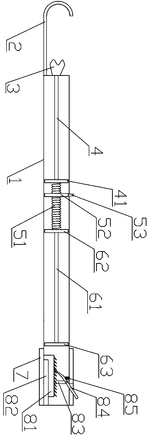
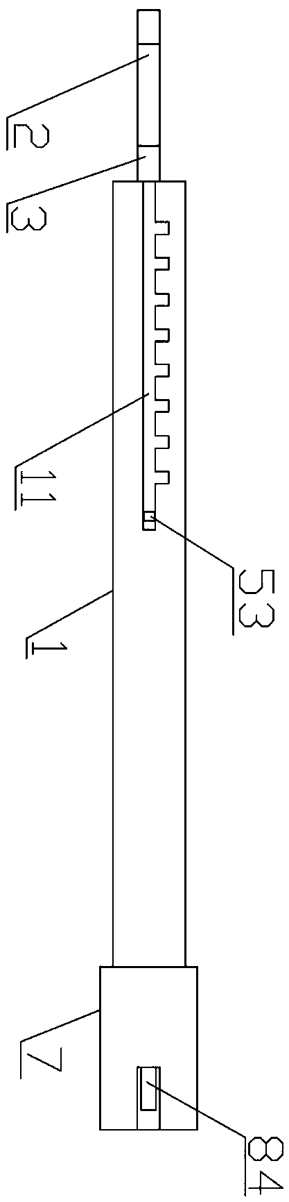
[0020] like Figure 1-2 As shown, a snap-press insulating locking rod for live work includes a hollow cylindrical outer insulating rod 1, a fixed locking hook 2 arranged at one end of the outer insulating rod 1, a clamping mechanism and a locking mechanism arranged in the outer insulating rod 1. Mechanism; the outer insulating rod 1 is provided with an opening at the end far away from the fixed locking hook 2, and the end of the outer insulating rod 1 close to the fixed locking hook is provided with a through hole;

[0021] The clamping mechanism includes a first support rod 4, a second support rod 61 and a Y-shaped movable lock head 3. The movable lock head 3 is arranged near one end of the fixed lock hook 2, and one end of the first support rod 4 stretches out from the through hole and The movable lock head 3 is fixedly connected, and the first support rod 4 is provided with a first stop 41 near one end of the second support rod 61, and the second support rod 61 is provided ...


PUM


Abstract

The invention belongs to the technical field of distribution line hot-line tools, and particularly relates to an elastic pressing type hot-line work insulating lock rod. The insulating lock rod comprises a hollow cylindrical outer insulating rod, a fixing lock hook arranged at one end of the outer insulating rod, a clamping mechanism arranged in the outer insulating rod and a locking mechanism, wherein the outer insulating rod is provided with an opening at the end away from the fixing lock hook, and the outer insulating rod is provided with a through hole in the end close to the fixing lock hook. According to the invention, a locking wire can be rapidly disassembled and assembled under the hot-line work condition, the operation is flexible, the operation position contacted with the hot-line cable wire is convenient to change, the insulating lock rod has the characteristics of simple structure and convenient use.

Description

technical field [0001] The invention belongs to the technical field of live tools for power distribution lines, and in particular relates to a snap-press insulating locking bar for live work. Background technique [0002] The insulating locking rod is one of the necessary tools in the live work of 10kV distribution lines. The existing insulating locking rod is a rotary movable head insulating locking rod, which is extremely inconvenient to operate in specific work, often resulting in the locking of the lock and the loosening of the wire Phenomena, it is easy to cause accident safety hazards, and the operation intensity is high, which is extremely inconvenient. [0003] The Chinese patent with the publication number CN208190117U discloses an insulating lock bar for live work, including a fixing seat, a cavity is opened in the fixing seat, a clamping plate is arranged in the cavity, and one side wall of the clamping plate is A threaded rod is fixedly connected, and the end of...

Claims


Application Information

Patent Timeline
IPC IPC(8): H02G1/02
CPCH02G1/02
Inventor 甘慧勇李佳宇王洪涛徐玉良余文丹王向伟高玉强段彦竹狄儒罗涛魏辉峰李明赵正华琚文婕陈璞颜炳达赵志好
Owner 国网河南省电力公司辉县市供电公司
Why Eureka
Try Eureka