
Slave cylinder for clutch release mechanism

A separation mechanism and clutch technology, applied in clutches, fluid-driven clutches, mechanically-driven clutches, etc., can solve the problems of quality and difficulty in forming the axial length of the outer sleeve.

Pending Publication Date: 2020-07-28
FTE汽车有限责任公司
View PDF8 Cites 0 Cited by
  • Summary
  • Abstract
  • Description
  • Claims
  • Application Information

AI Technical Summary

Problems solved by technology

[0006] However, in a compact slave cylinder, it is difficult to form the outer sleeve to the required axial length
The resulting ratio of axial length to wall thickness of the outer sleeve can then lead to quality issues

Method used


Image

  • Slave cylinder for clutch release mechanism
  • Slave cylinder for clutch release mechanism
  • Slave cylinder for clutch release mechanism

Examples


Embodiment Construction

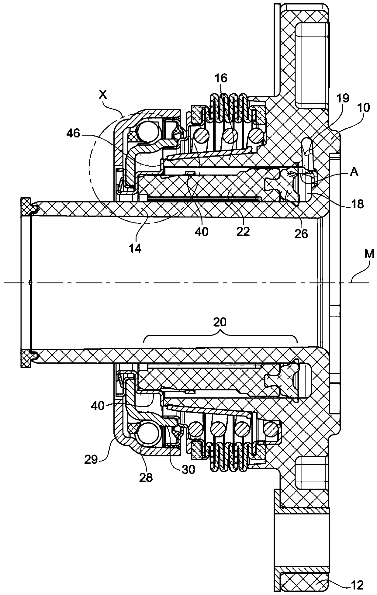
[0017] figure 1 Slave cylinder 1 is shown. It is a central separating device with a central axis M. Slave cylinder 1 is "CSC", which means concentric slave cylinder. The slave cylinder 1 is concentric with a transmission shaft such as an input shaft of a gearbox.

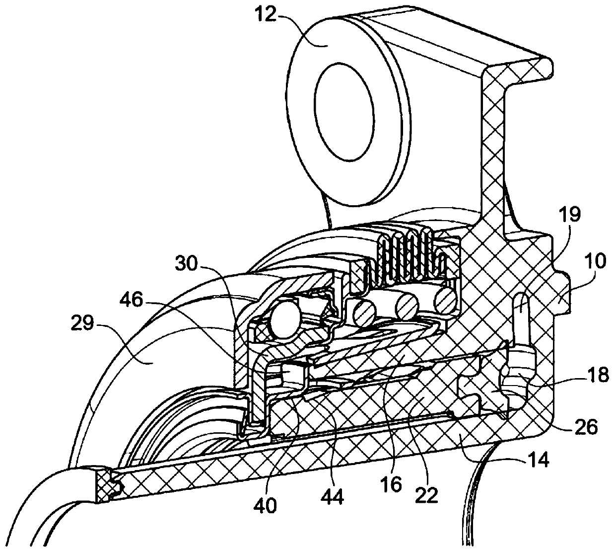
[0018] The slave cylinder 1 has a housing 10 with a mounting flange 12 , an inner sleeve 14 and an outer sleeve 16 . An annular space is formed between the inner sleeve 14 and the outer sleeve 16, which is formed by the material of the housing 10 at the "base" (in figure 1 to the right of ) is closed. Piston 20 (see figure 1 ) are movably arranged in the annular space.

[0019] The annular space thus forms an annular fluid chamber 18 , the inlet opening not shown here. If the fluid chamber 18 is filled with fluid and the pressure in the fluid chamber increases, the piston 20 acts on the left side (relative to figure 1 ).

[0020] The housing is usually an injection molded part made of plastic.

[0021] The...


PUM


Abstract

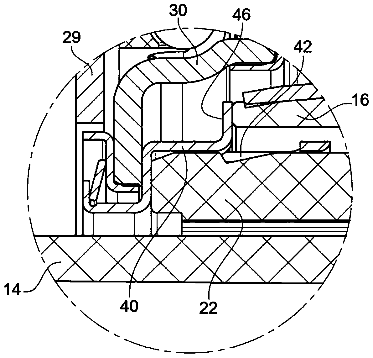
The invention relates to a slave cylinder (1) for a clutch release mechanism. The slave cylinder (2) has a housing (10). In the housing, an annular fluid chamber (18) is formed between the inner sleeve (14) and the outer sleeve (16), wherein the fluid chamber (18) is provided with an inlet opening (19) for the fluid, the invention relates to a valve having an annular piston (20) which is displaceably arranged in a fluid chamber (18), a seal (26) attached to the piston (20) on a side facing the inlet opening (19), and a support ring (40), and a release bearing attached to the piston (20) and supporting the release bearing (28), characterized in that the support ring (40) is provided with at least one stop tab (46) which extends radially outward and can abut against the end side of the outersleeve (16), thereby defining a maximum retracted position of the piston (20), in which position the axial distance of the seal (26) from the inlet opening (19) is greater than zero.

Description

technical field [0001] The invention relates to a slave cylinder for a clutch release mechanism, having a housing in which an annular fluid chamber is formed between an inner sleeve and an outer sleeve, wherein the fluid chamber is provided with an inlet opening for fluid , with an annular piston displaceably arranged in the fluid chamber, with a seal attached to the piston on the side facing the inlet opening, and with a support ring, which is attached to the piston and supports the release bearing. Background technique [0002] Slave cylinders are used to switch friction clutches in the drive train of a motor vehicle from an engaged, ie, non-actuated, position to a disengaged, ie, actuated position. To this end, the fluid chamber is connected via lines to a master cylinder in which the actuation force, for example from a clutch pedal, is converted into fluid pressure. [0003] The housing of the slave cylinder is usually attached to the clutch cover or transmission cover....

Claims


Application Information

Patent Timeline
Patent Type & Authority Applications(China)
IPC IPC(8): F16D25/12
CPCF16D25/14F16D23/14F16D25/083
Inventor J.格尼普
Owner FTE汽车有限责任公司
Learn More