
Uplink power control method and device for terminal equipment

A technology of terminal equipment and transmit power, applied in the field of communication, can solve problems such as low signal strength, poor control accuracy, affecting communication quality, etc., to achieve the effect of improving control accuracy, eliminating signal interference, and avoiding near-far effects

Active Publication Date: 2021-12-28
航天行云科技有限公司
View PDF0 Cites 0 Cited by
  • Summary
  • Abstract
  • Description
  • Claims
  • Application Information

AI Technical Summary

Problems solved by technology

[0003] In practical applications, it is found that when there are many ground terminal devices reporting messages to the satellite at the same time, after the messages sent by some ground terminal devices arrive at the satellite, the signal strength is lower than that sent by other ground terminal devices. Then it is possible to "submerge" in these messages with high signal strength, forming a "near and far effect", resulting in the inability to complete the communication process, which obviously affects the communication quality
[0004] In the existing related technology, the uplink power can be adjusted on the side of the ground terminal equipment, and then the signal strength of the message sent by the ground terminal equipment to the target satellite can be adjusted, so that the multiple messages received by the target satellite have the same signal strength. , to avoid the "near and far effect", but its frequent error is large and the control accuracy is not good, which will still affect the communication quality between the ground terminal equipment and the target satellite

Method used


Image

  • Uplink power control method and device for terminal equipment
  • Uplink power control method and device for terminal equipment
  • Uplink power control method and device for terminal equipment

Examples


Embodiment Construction

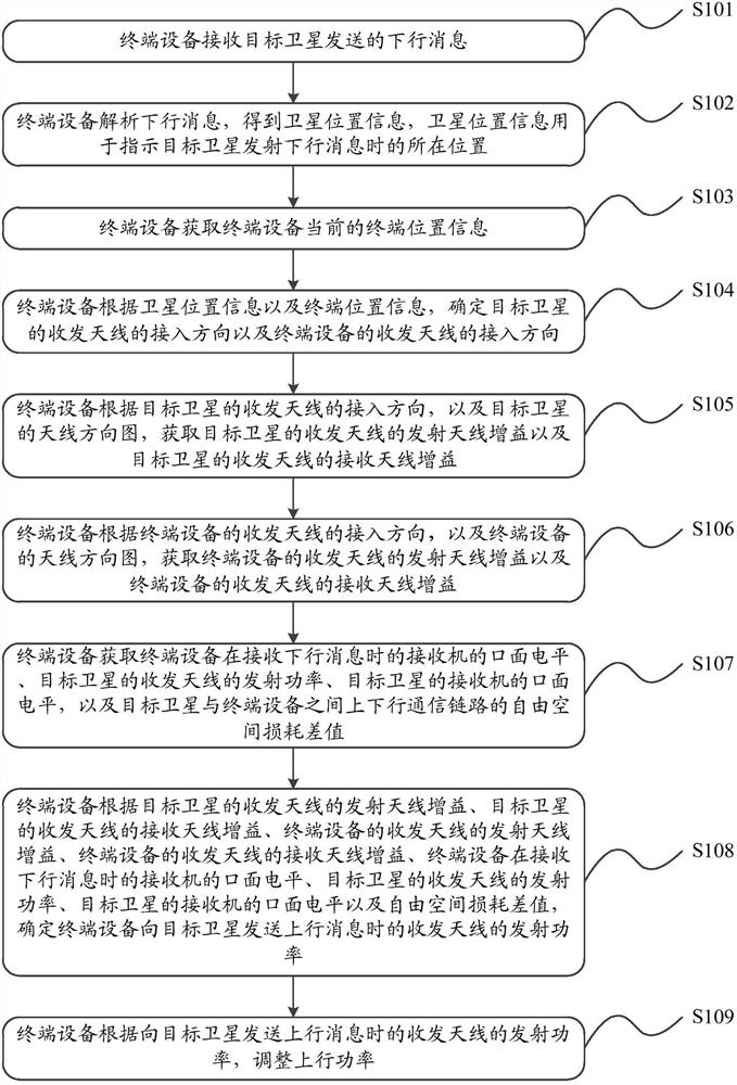
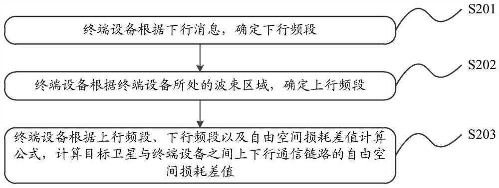
[0074] The embodiment of the present application provides a terminal device uplink power control method and device, which are used to improve the control accuracy during the control process of the terminal device's uplink power, and then accurately control the signal strength when the message sent by the terminal device reaches the target satellite , thus ensuring that the signal strengths of multiple messages received by the target satellite are consistent, avoiding the "near and far effect", and ensuring the communication quality between multiple terminal devices and the target satellite.

[0075] The following will clearly and completely describe the technical solutions in the embodiments of the application with reference to the drawings in the embodiments of the application. Apparently, the described embodiments are only some of the embodiments of the application, not all of them. Based on the embodiments in this application, all other embodiments obtained by those skilled ...


PUM


Abstract

The embodiment of the present application provides an uplink power control method and device for a terminal device. By accurately determining the off-axis angle of the pattern of the transmitting and receiving antenna of the current target satellite, and the off-axis angle of the pattern of the transmitting and receiving antenna of the current terminal device, the antenna can be combined. The pattern can accurately determine the antenna gain, so that the transmission power of the transceiver antenna can be more accurately determined when the terminal device sends an uplink message to the target satellite, and the uplink power control can be completed during the communication process between the terminal device and the target satellite , improve the control accuracy, and then accurately control the signal strength of the message sent by the terminal device when it reaches the target satellite, so as to ensure that the signal strength of multiple messages received by the target satellite is consistent, avoiding the "near and far effect", eliminating After signal interference, the communication quality between multiple terminal devices and target satellites can be guaranteed.

Description

technical field [0001] The present application relates to the field of communications, and in particular to a method and device for controlling uplink power of terminal equipment. Background technique [0002] After satellites are launched into space, they have a wide range of uses, such as astronomical observation, communication broadcast, scientific research, ground monitoring, etc. During the working process of the satellite, it can communicate with the ground terminal equipment, and the satellite can also forward business data between different terminal equipment. [0003] In practical applications, it is found that when there are many ground terminal devices reporting messages to the satellite at the same time, after the messages sent by some ground terminal devices arrive at the satellite, the signal strength is lower than that sent by other ground terminal devices. Then it is possible to "submerge" in these messages with high signal strength, forming a "near and far ...

Claims


Application Information

Patent Timeline
Patent Type & Authority Patents(China)
IPC IPC(8): H04B7/185
CPCH04B7/18543
Inventor 王璇喻竹希
Owner 航天行云科技有限公司
Learn More