Ultrasonic suspension transmission distance compensating method based on excitation phase position
A technology of transmission distance and compensation method, which is applied in the direction of conveyors, conveyor objects, transportation and packaging, etc., which can solve the problems of complex adjustment process, difficult to ensure the accuracy of support length adjustment, and difficult to be equivalent to cross-section
- Summary
- Abstract
- Description
- Claims
- Application Information
AI Technical Summary
Problems solved by technology
Method used
Image
Examples
specific Embodiment approach 1
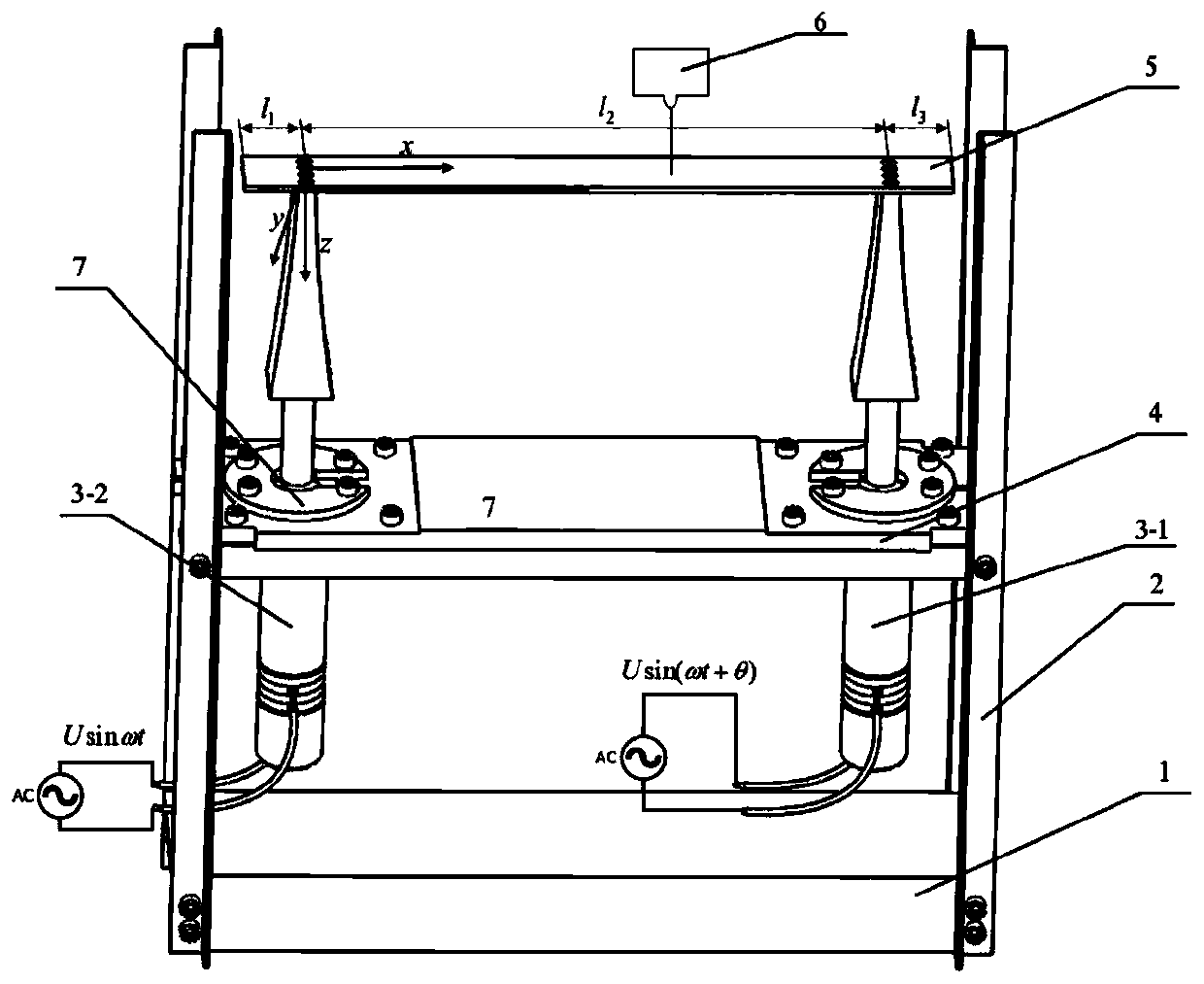
[0031] Combine below Figure 1-6 To illustrate this embodiment, a method for compensating the transmission distance of ultrasonic levitation based on the excitation phase includes the following steps:
[0032] Step 1: Build an ultrasonic traveling wave suspension transmission device, apply two excitation signals with the same amplitude and frequency to the ultrasonic transducer I3-1 and the ultrasonic transducer II3-2 respectively, and there is a phase difference I between the two excitation signals;
[0033]Step 2: Analyze the vibration displacement of the vibrating elastic body 5, set the distance between the two support points of the vibrating elastic body 5 and the corresponding spatial phase difference is φ, set the signals of ultrasonic transducer Ⅰ3-1 and ultrasonic transducer Ⅱ3-2 The phase difference I in time is θ, and the relationship between the excitation signal phase difference IIθ and the spatial phase difference φ under the condition that the maximum vibration ...
specific Embodiment approach 2
[0037] Combine below Figure 1-6 Describe this embodiment, this embodiment will further explain Embodiment 1, the method for solving the relationship between the excitation signal phase difference IIθ and the spatial phase difference φ under the condition that the maximum vibration displacement and the minimum vibration displacement at any position on the vibrating elastic body 5 are equal is: At any time t, the vibration displacement equation f(x, t) of the particle located at x on the vibrating elastic body 5 along the z direction, from the vibration displacement equation f(x, t), the amplitude expression A(t ), looking for the extremum value of the amplitude on the vibrating elastic body 5, let Bring the solution conditions into the amplitude expression A(t) to find the maximum vibration displacement A max (θ, φ) and minimum vibration displacement A min (θ,φ), solve for A max (θ,φ)=A min (θ, φ), obtain the maximum vibration displacement at any position on the vibrating...
specific Embodiment approach 3
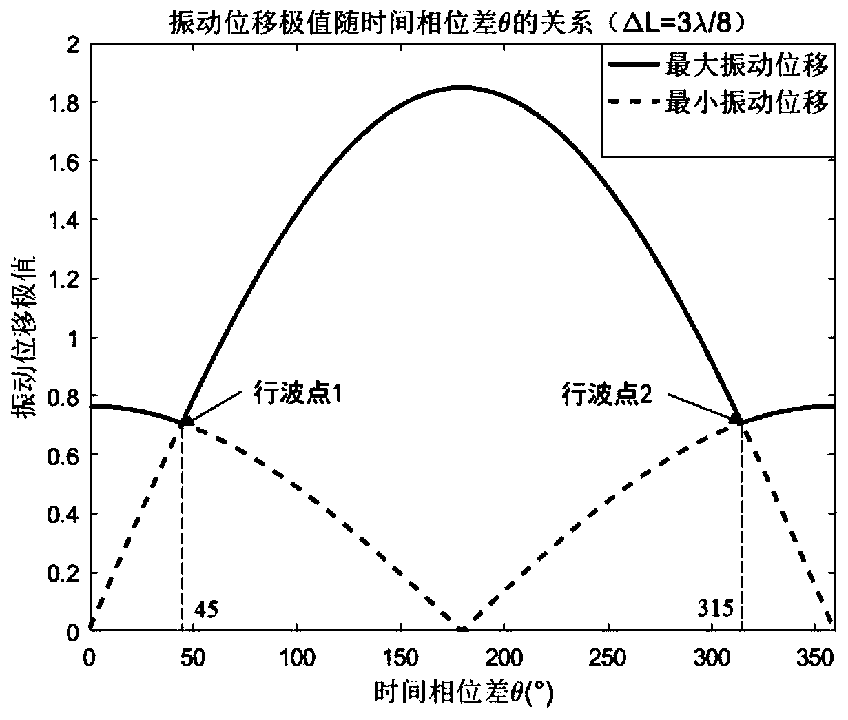
[0078] Combine below Figure 1-6 Describe this embodiment. This embodiment will further explain Embodiment 2. From the relational expression obtained in Step 2, find out the relationship between the time phase difference IIθ and the space phase difference φ in the traveling wave mode, and the vibrating elastic body 5 supports the distance l 2 =mλ+ΔL, Spatial phase φ = kl 2 =2mπ+Δφ, when ΔL figure 2 Shown l 2 is the supporting distance of the vibrating elastic body 5, l 1 and l 3is the shortest distance from the two supporting positions along the length of the vibrating elastic body 5 to the edge of the vibrating elastic body 5, no matter how the supporting distance L of the vibrating elastic body 5 changes, the spatial phase Δφ is compensated by the excitation phase θ, so that a pure traveling wave can be realized transmission. Drawing the change curve of the maximum vibration displacement of the vibrating elastic body 5 with the phase difference Ⅱθ can guide the experim...
PUM
 Abstract
Description
Claims
Application Information
 - R&D Engineer
- R&D Manager
- IP Professional
- Industry Leading Data Capabilities
- Powerful AI technology
- Patent DNA Extraction
Browse by: Latest US Patents, China's latest patents, Technical Efficacy Thesaurus, Application Domain, Technology Topic, Popular Technical Reports.
© 2024 PatSnap. All rights reserved.Legal|Privacy policy|Modern Slavery Act Transparency Statement|Sitemap|About US| Contact US: help@patsnap.com


