
Limiting structure of insulated bus bridge

A technology of limiting structure and insulated busbar, which is applied in the installation of busbar, fully enclosed busbar device, cable installation, etc., which can solve the problems of inconvenient laying and maintenance of busbar and easy confusion of busbar

Pending Publication Date: 2020-07-10
RUGAO TIANAN ELECTRIC TECH
View PDF0 Cites 1 Cited by
  • Summary
  • Abstract
  • Description
  • Claims
  • Application Information

AI Technical Summary

Problems solved by technology

[0003] The purpose of the present invention is to provide a position-limiting structure of an insulated busbar bridge, which has the advantage of position-limiting and solves the problem of confusion between busbars due to the large number of busbars arranged in the bridge frame, thereby bringing troubles to the laying and maintenance of the busbars. Inconvenience

Method used


Image

  • Limiting structure of insulated bus bridge
  • Limiting structure of insulated bus bridge
  • Limiting structure of insulated bus bridge

Examples


Embodiment Construction

[0016] The following will clearly and completely describe the technical solutions in the embodiments of the present invention with reference to the accompanying drawings in the embodiments of the present invention. Obviously, the described embodiments are only some, not all, embodiments of the present invention. Based on the embodiments of the present invention, all other embodiments obtained by persons of ordinary skill in the art without making creative efforts belong to the protection scope of the present invention.

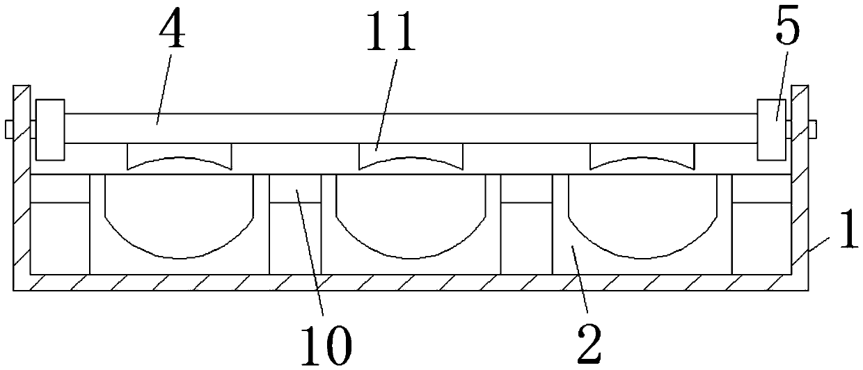
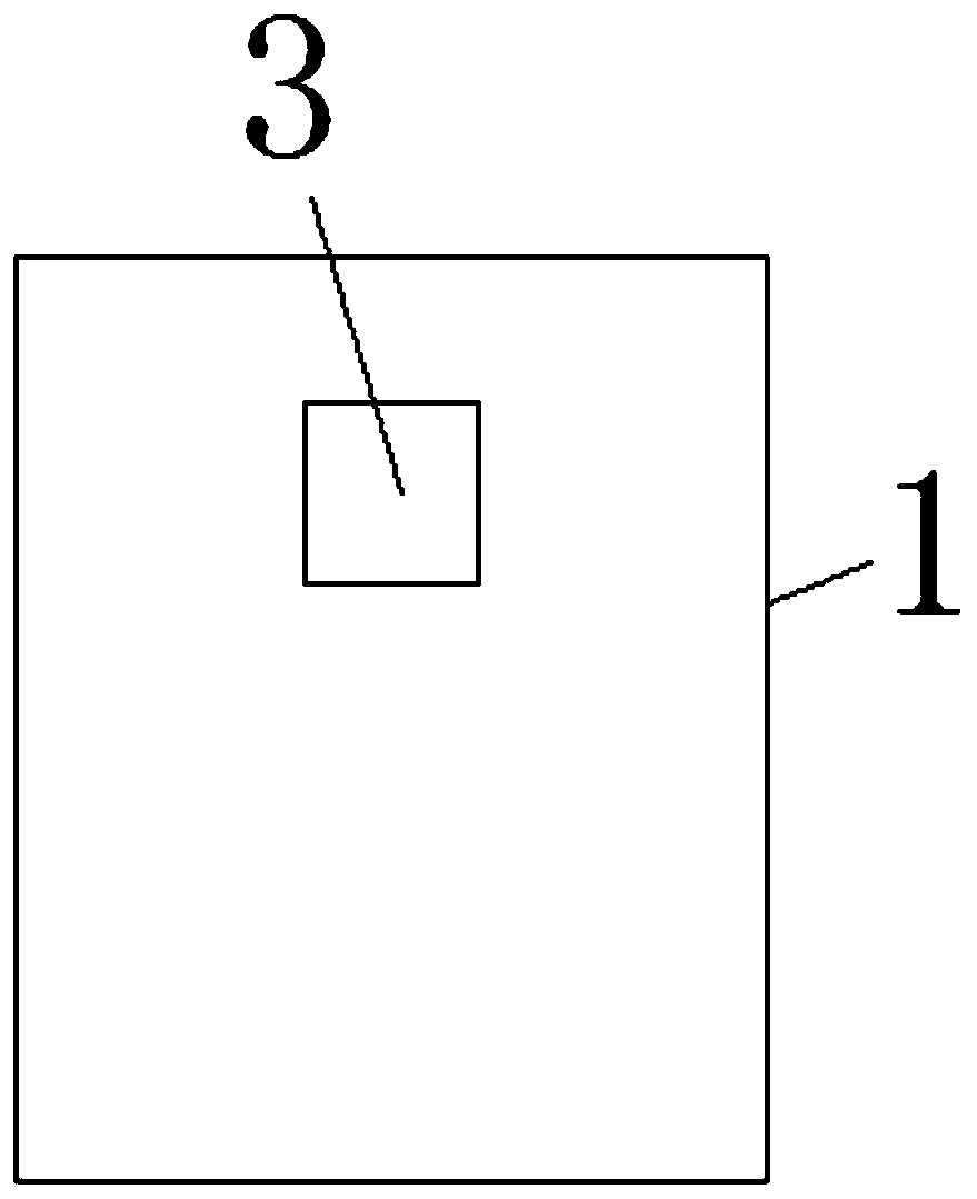
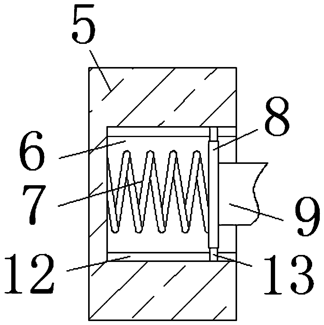
[0017] Groove body 1 of the present invention, limiting groove 2, clamping hole 3, pressure plate 4, fixed block 5, spring groove 6, return spring 7, movable plate 8, clamping rod 9, fixed rod 10, positioning plate 11, positioning groove 12 The components of the limit block and the limit block 13 are common standard parts or components known to those skilled in the art, and their structures and principles can be known to those skilled in the art through technic...


PUM


Abstract

The invention discloses a limiting structure of an insulated bus bridge. The device comprises a groove body and a pressing plate, a limiting groove is fixedly connected to the bottom of an inner cavity of the groove body, clamping holes are formed in the two sides of the groove body, fixing blocks are fixedly connected to the two sides of the pressing plate, spring grooves are formed in the surfaces of the fixing blocks, reset springs are fixedly connected to the inner walls of the spring grooves, and movable plates are fixedly connected to one ends of the reset springs. A bus is placed through the limiting groove; a positioning plate at the bottom of the pressing plate fixes the upper surface of the bus; the two ends of the clamping rod fix inner cavities of the blocks; the limiting plateis arranged in the clamping holes and extends to the inner cavity of the clamping hole under the driving of the reset elastic force of the reset springs, so that the pressing plate is fixed, the effect of limiting the bus by the positioning plate and the limiting groove is achieved, and the problem that the buses tend to be disordered and inconvenience is brought to laying and overhauling of thebuses due to more arrangement of the buses in the bridge is solved.

Description

technical field [0001] The invention relates to the technical field of busbar bridges, in particular to a position-limiting structure of insulated busbar bridges. Background technique [0002] Busbar bridge is a new type of distribution wire application. Compared with traditional cables, it fully demonstrates its superiority in high current transmission. At the same time, due to the adoption of new technologies and new processes, it greatly reduces The contact resistance and temperature rise at the connection point and the branch port socket, but because the busbars are arranged more in the bridge frame, there is easy confusion between the busbars, which brings inconvenience to the laying and maintenance of the busbars. Contents of the invention [0003] The purpose of the present invention is to provide a position-limiting structure of an insulated busbar bridge, which has the advantage of position-limiting and solves the problem of confusion between busbars due to the la...

Claims


Application Information

Patent Timeline
Patent Type & Authority Applications(China)
IPC IPC(8): H02G5/00H02G5/06
CPCH02G5/00H02G5/06
Inventor 石朗琪
Owner RUGAO TIANAN ELECTRIC TECH
Learn More