Safety aerial photography unmanned aerial vehicle
A UAV and safety technology, applied in the field of aerial photography drones, can solve the problems of poor shock absorption effect of aerial photography drones and damage to the shooting device, and achieve the effect of good shock absorption effect, avoiding contact with the ground, and avoiding damage.
- Summary
- Abstract
- Description
- Claims
- Application Information
AI Technical Summary
Problems solved by technology
Method used
Image
Examples
Embodiment 1
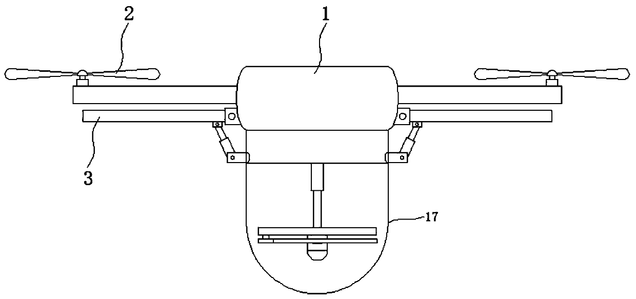
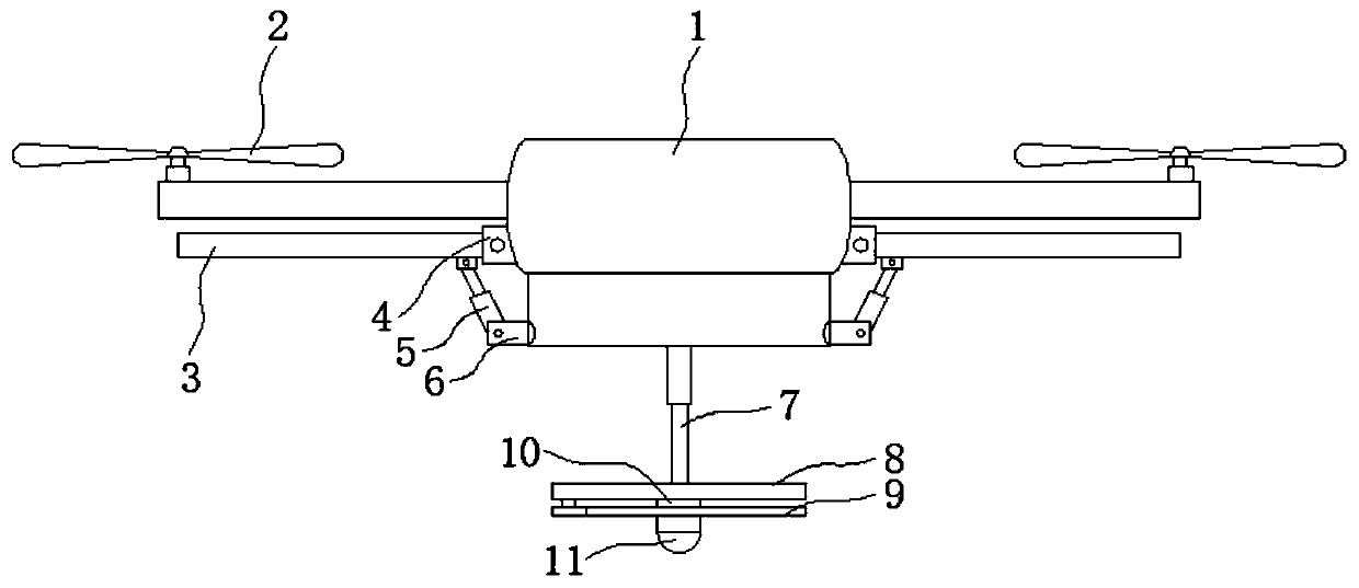
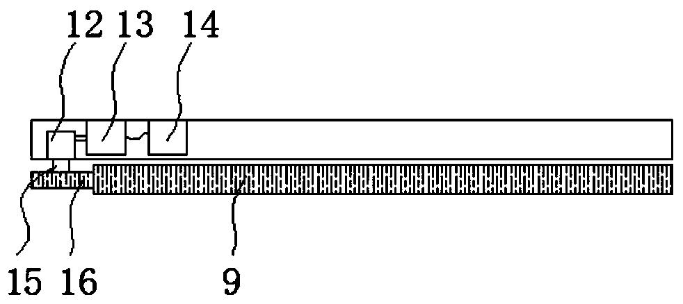
[0027] see Figure 1-5 , in an embodiment of the present invention, a safety aerial photography UAV includes a body 1, a wing 2 is installed on the outside of the body 1, and a supporting leg hinge seat 4 and a push rod 5 connecting seat are installed on the outside of the body 1. A shock-absorbing support leg 3 is hinged on the support leg transfer seat, a push rod 5 is hinged on the push rod hinge seat 6, and one end of the push rod 5 away from the push rod hinge seat 6 is hinged to the shock-absorbing support leg 3, and the A lifting rod 7 is installed at the bottom of the body 1, and a fixed plate 8 is installed at the bottom of the lifting rod 7. The bottom end of the fixed plate 8 is connected with a driven gear plate 9 through a bearing 10, and the fixed plate 8 is set as a hollow structure. , the fixed plate 8 is provided with a reducer 12, a motor 13 and a battery 14, the output torque of the motor 13 is connected to the reducer, the reducer 12 is connected to the dri...
Embodiment 2
[0030] see Figure 2-4, in an embodiment of the present invention, a safety aerial photography UAV includes a body 1, a wing 2 is installed on the outside of the body 1, and a supporting leg hinge seat 4 and a push rod 5 connecting seat are installed on the outside of the body 1. A shock-absorbing support leg 3 is hinged on the support leg transfer seat, a push rod 5 is hinged on the push rod hinge seat 6, and one end of the push rod 5 away from the push rod hinge seat 6 is hinged to the shock-absorbing support leg 3, and the A lifting rod 7 is installed at the bottom of the body 1, and a fixed plate 8 is installed at the bottom of the lifting rod 7. The bottom end of the fixed plate 8 is connected with a driven gear plate 9 through a bearing 10, and the fixed plate 8 is set as a hollow structure. , the fixed plate 8 is provided with a reducer 12, a motor 13 and a battery 14, the output torque of the motor 13 is connected to the reducer, the reducer 12 is connected to the driv...
PUM
 Abstract
Description
Claims
Application Information
 - R&D Engineer
- R&D Manager
- IP Professional
- Industry Leading Data Capabilities
- Powerful AI technology
- Patent DNA Extraction
Browse by: Latest US Patents, China's latest patents, Technical Efficacy Thesaurus, Application Domain, Technology Topic, Popular Technical Reports.
© 2024 PatSnap. All rights reserved.Legal|Privacy policy|Modern Slavery Act Transparency Statement|Sitemap|About US| Contact US: help@patsnap.com


