A high temperature resistant and anti-corrosion cyclone shear gas-liquid separator

A gas-liquid separator, shearing technology, applied in separation methods, dispersed particle separation, chemical instruments and methods, etc., can solve the problem of affecting the service life of 304 stainless steel gas-liquid separator, application effect discount, preparation cost increase, etc. question

Active Publication Date: 2021-08-24
苏州汇博龙环保科技有限公司
View PDF33 Cites 2 Cited by
  • Summary
  • Abstract
  • Description
  • Claims
  • Application Information

AI Technical Summary

Problems solved by technology

However, at present, the main body of the gas-liquid separator and the internal components of the separator usually have three obvious defects, which greatly reduce the application effect: the first is the large number of moving plates, resulting in high energy consumption and low separation efficiency, and the parts are easily damaged ; Second, to make the separator, the main material used is not anti-corrosion material, which is basically economical 304 stainless steel. Due to the synthesis process of chemical industry, medicine and pesticide, it is synthesized in a strongly corrosive acidic medium, especially It is synthesized in hydrochloric acid medium, which seriously affects the service life of the 304 stainless steel gas-liquid separator. Using dual-phase steel and titanium to prepare the gas-liquid separator will increase the preparation cost sharply, and the user cannot afford it; Third, if Among the production materials of the cyclone shear separation component (or other parts inside the main body of the separator), if corrosion-resistant FRP is used for corrosion protection, high-temperature epoxy resin at 150-280°C is used for corrosion protection. Practice has proved that due to the high speed of the gas-liquid separator , large temperature difference and large pressure difference, it is very easy to cause local peeling and peeling of the anti-corrosion layer, and then cause serious internal corrosion and strength decline, and the equipment is paralyzed

Method used

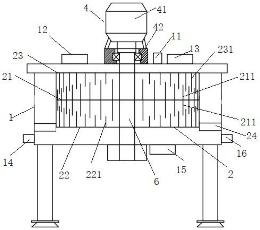
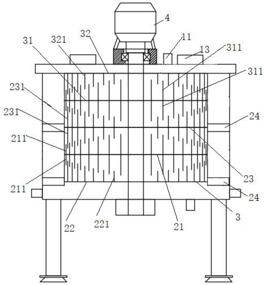
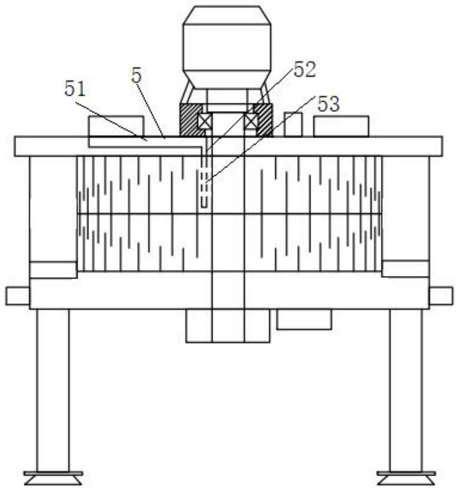

Image

  • A high temperature resistant and anti-corrosion cyclone shear gas-liquid separator
  • A high temperature resistant and anti-corrosion cyclone shear gas-liquid separator
  • A high temperature resistant and anti-corrosion cyclone shear gas-liquid separator

Examples


Embodiment Construction

[0078] The preferred embodiments of the present invention will be described below in conjunction with the accompanying drawings. It should be understood that the preferred embodiments described here are only used to illustrate and explain the present invention, and are not intended to limit the present invention.

[0079] In addition, in the present invention, descriptions such as "first", "second" and so on are used for description purposes only, and do not refer to the meaning of order or sequence, nor are they used to limit the present invention, but are only for the purpose of distinguishing the following The components or operations described by the same technical terms are only used, but should not be understood as indicating or implying their relative importance or implying the number of indicated technical features. Thus, the features defined as "first" and "second" may explicitly or implicitly include at least one of these features. In addition, the technical solution...


PUM


Abstract

The invention provides a high-temperature-resistant and anti-corrosion cyclone-shear type gas-liquid separator, which includes a first or second cyclone-shear type separation standard module assembly, which respectively consists of a first disc body, a second disc body and a second disc body. Composed of three discs, or composed of the first disc, the second disc, the third disc, the fourth disc and the fifth disc, the first or second cyclone shear separation standard module components are all along the main axis The axial interval is connected to the main shaft. When the rotary separator is rotating at high speed, the liquid is continuously circulated and impacted by the centrifugal force of the rotary separator and the counterflow of the gas, so that the solute and solvent are separated effectively and efficiently. The gas-liquid separator disc and main body Both the main shaft and the main shaft are made of corresponding anti-corrosion engineering materials. This device has the advantages of good anti-corrosion performance, simple operation, and low energy consumption. device.

Description

technical field [0001] The invention relates to the technical field of gas-liquid separators, in particular to a high-temperature-resistant, corrosion-resistant, swirl-flow shearing gas-liquid separator. Background technique [0002] The basic principle of high-gravity engineering technology is to use the unique flow behavior of multi-phase flow systems under high-gravity conditions to strengthen the relative velocity and mutual contact between phases. Among them, the high-gravity rotation generates strong centrifugal force, and the liquid is torn into Small liquid droplets, liquid films and liquid filaments flow outward at high speed to generate a large number of rapidly renewed surface areas, thereby realizing efficient mass transfer, heat transfer and chemical reaction processes. The high-gravity separation technology is a new technology to strengthen the multiphase flow transfer and reaction process, and the centrifugal force field is used for phase separation. [0003]...

Claims


Application Information

Patent Timeline
Patent Type & Authority Patents(China)
IPC IPC(8): B01D45/12
CPCB01D45/12
Inventor 刘景明刘婉婷
Owner 苏州汇博龙环保科技有限公司
Why Eureka
Try Eureka