
A rice milling device

A technology of outer cylinder and inner cylinder, which is applied in the field of rice processing, can solve problems such as friction obstruction and affecting rice husking, and achieve the effects of reducing broken rice, improving falling efficiency, and simple structure

Active Publication Date: 2021-07-30
重庆穗花食为天粮油有限公司
View PDF0 Cites 0 Cited by
  • Summary
  • Abstract
  • Description
  • Claims
  • Application Information

AI Technical Summary

Problems solved by technology

But because the rice milling machine processes a large amount of paddy simultaneously in the course of work, there are many shells that have been taken off and the shells still exist in the rice milling machine. The friction between the rice machine or other rice will cause obstacles, thus affecting the husking of rice

Method used


Image

  • A rice milling device
  • A rice milling device
  • A rice milling device

Examples


Embodiment 1

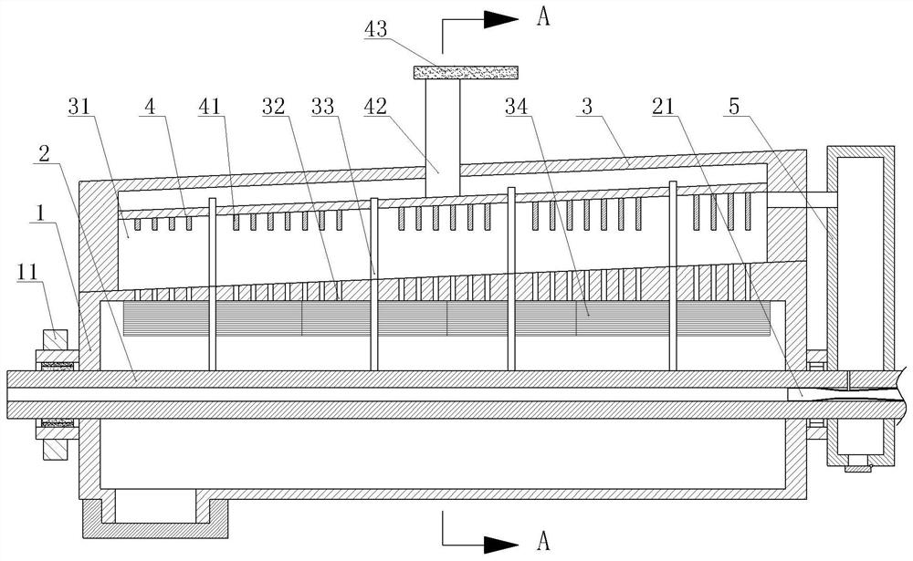
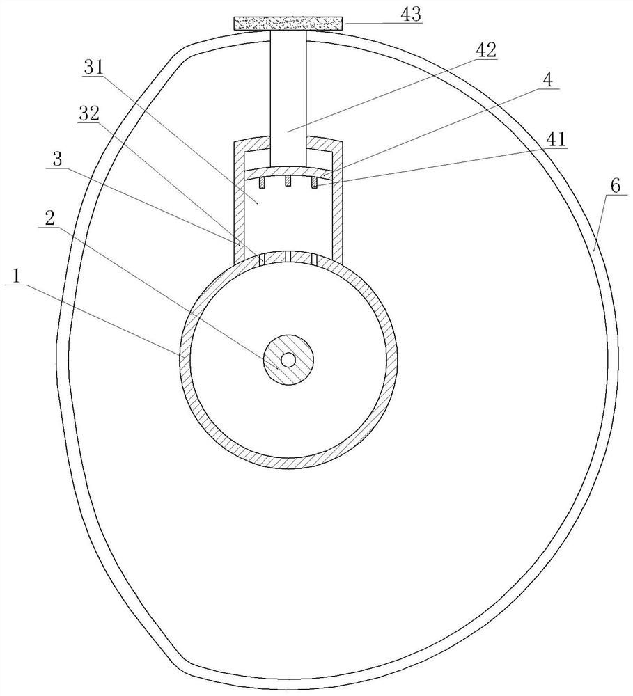
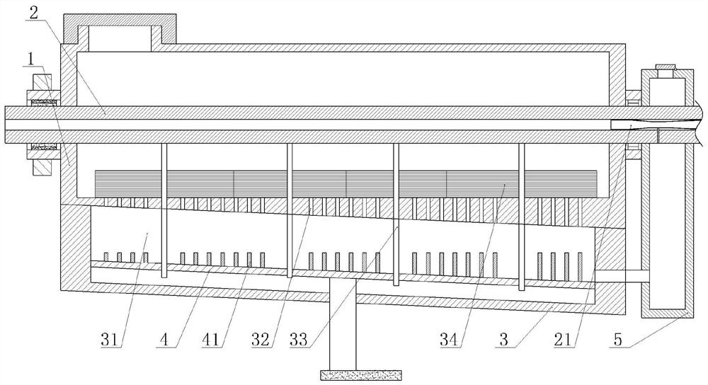
[0034] A rice milling device, such as figure 1 As shown, it includes a frame, a driving part, an outer cylinder 1 and an inner cylinder 2 located in the outer cylinder 1. In this embodiment, the outer cylinder 1 and the inner cylinder 2 are coaxial, and the two ends of the outer cylinder 1 are welded with installation shafts. The end of the installation shaft away from the outer tube 1 runs through the frame and is matched with the frame in clearance. The mounting shaft on the left side is connected with the driven gear 11 by a flat key, and the driving part is fixed on the frame by bolts. Gear 11 meshes with the driving gear. The bottom of the outer cylinder 1 is provided with a feeding port and a feeding port cover. The feeding port cover is threadedly matched with the feeding port to close the feeding port; A one-way intake valve for air intake in barrel 1.

[0035] The top of the outer cylinder 1 is welded with a separation barrel 3 with the opening facing downward. Th...

Embodiment 2

[0045] On the basis of Example 1, such as Figure 4 As shown, the part of the guide rod in this embodiment located between the outer cylinder 1 and the inner cylinder 2 is wave-shaped, and the rotating rod 33 is in clearance fit with the piston 4 to ensure that the rotating rod 33 can rotate relative to the piston 4 . Inner tube 2 outer wall is provided with annular guide groove 23, and guide groove 23 internal gaps are matched with spherical guide block, and the diameter of guide block is greater than the diameter of rotating rod 33, and the lower end of rotating rod 33 stretches in the guide groove 23 and connects with guide block. welding. The lower end of the guide rod is fixed with a first bevel gear through a flat key, and a second bevel gear 22 meshing with the first bevel gear is welded on the side wall of the guide groove 23 .

[0046] When the outer cylinder 1 in this solution rotates, the rotating rod 33 rotates with the outer cylinder 1, and the first bevel gear m...


PUM


Abstract

The invention relates to the field of rice processing, and specifically discloses a rice milling device. It includes a driving part, an outer cylinder and an inner cylinder located in the outer cylinder. The outer cylinder is provided with a closeable feeding port; the side wall of the outer cylinder is fixed with a separation barrel with an opening facing the outer cylinder. There is a separation chamber in the separation barrel, and the outer cylinder The side wall is provided with a number of separation holes connecting the separation chamber with the inner cavity of the outer cylinder. A piston is slidingly sealed in the separation chamber, and a number of sealing columns are fixed on the end of the piston facing the inner cylinder. The sealing columns correspond to the separation holes one by one and are sealed. The column is slidably connected with the separation hole. The end of the piston away from the inner cylinder is fixed with a push rod. The push rod penetrates the side wall of the separation barrel and is slidably connected with the separation side wall. Located on the side of the piston away from the inner cylinder. The rice milling device of the present invention separates the peeled shell while shelling, so as to avoid the friction between the shell and other rice or rice mills to hinder the shell.

Description

technical field [0001] The invention relates to the field of rice processing, in particular to a rice milling device. Background technique [0002] After the rice is dried, it needs to go through the process of husking and whitening to remove the cortex and germ of the rice to get polished rice. The polished rice goes through a series of screening, weighing, and packaging processes to get rice that can be sold. Present husking and whitening are usually carried out by a rice mill. During rice milling, friction occurs between the rice and the inner wall of the rice mill or other rice, so that the outer shell of the rice falls off. But because the rice milling machine processes a large amount of paddy simultaneously in the course of work, there are many shells taken off and the shells still exist in the rice milling machine. The friction between the rice machine or other rice will cause obstacles, thereby affecting the husking of the rice. Contents of the invention [0003]...

Claims


Application Information

Patent Timeline
Patent Type & Authority Patents(China)
IPC IPC(8): B02B7/00B02B3/04B07B1/22B07B1/52B07B1/50
CPCB02B3/04B02B7/00B07B1/22B07B1/50B07B1/522
Inventor 袁泽兰
Owner 重庆穗花食为天粮油有限公司
Learn More