
Electronic detonator bridge wire mounting equipment

A technology for electronic detonators and installation equipment, applied in offensive equipment, weapon accessories, fuzes, etc., can solve problems such as low work efficiency, inconsistent with production concepts, and high difficulty, and achieve the effect of improving production efficiency

Pending Publication Date: 2020-06-30
东莞市弘腾自动化智能科技有限公司
View PDF7 Cites 2 Cited by
  • Summary
  • Abstract
  • Description
  • Claims
  • Application Information

AI Technical Summary

Problems solved by technology

[0004] Usually, the diameter of the bridge wire of a digital electronic detonator is confirmed in microns to ensure that the bridge wire has sufficient resistance. It is extremely difficult to install and connect such a small bridge wire to the bridge frame. Because the bridge wire is installed on the electronic detonator At present, the production of the installation of the bridge wire on the electronic detonator is mainly realized by manual operation, and then meets the setting requirements for the installation of the bridge wire in the industrial digital electronic detonator. This manual operation method is inefficient and time-consuming , laborious, does not conform to the production concept of modern industrial production

Method used


Image

  • Electronic detonator bridge wire mounting equipment
  • Electronic detonator bridge wire mounting equipment
  • Electronic detonator bridge wire mounting equipment

Examples


Embodiment Construction

[0027] In order to make the technical problems, technical solutions and beneficial effects to be solved by the present invention clearer, the present invention will be further described in detail below in conjunction with the accompanying drawings and embodiments. It should be understood that the specific embodiments described here are only used to explain the present invention, not to limit the present invention.

[0028] It should be noted that when a component is referred to as being “fixed on” or “disposed on” another component, it may be directly on the other component or indirectly on the other component. When an element is referred to as being "connected to" another element, it can be directly or indirectly connected to the other element.

[0029] It is to be understood that the terms "length", "width", "top", "bottom", "front", "rear", "left", "right", "vertical", "horizontal", "top" , "bottom", "inner", "outer" and other indicated orientations or positional relations...


PUM


Abstract

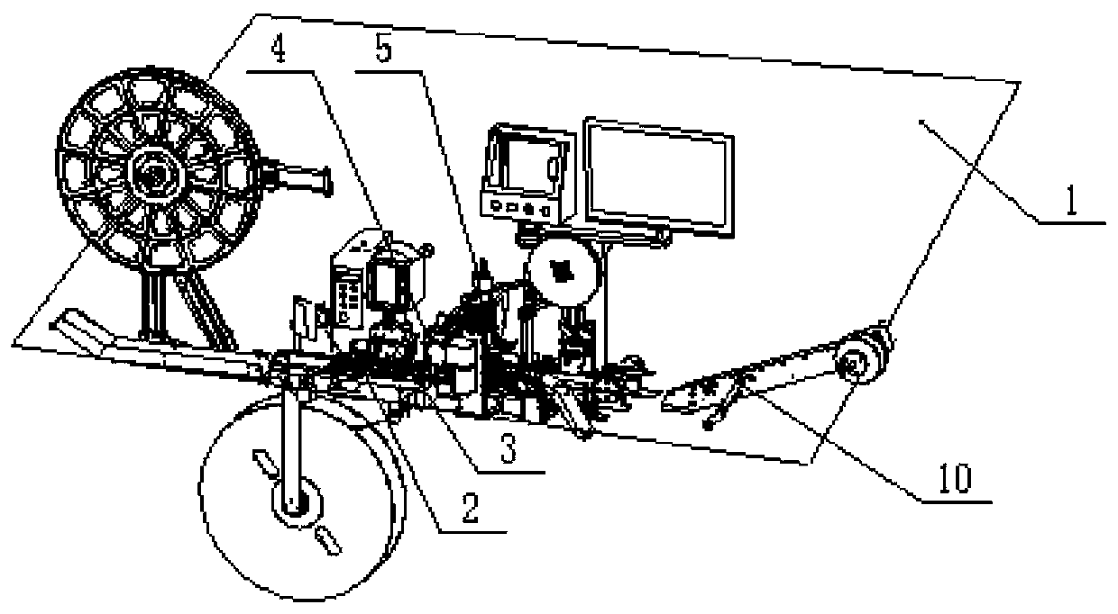
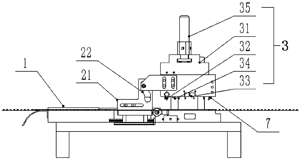
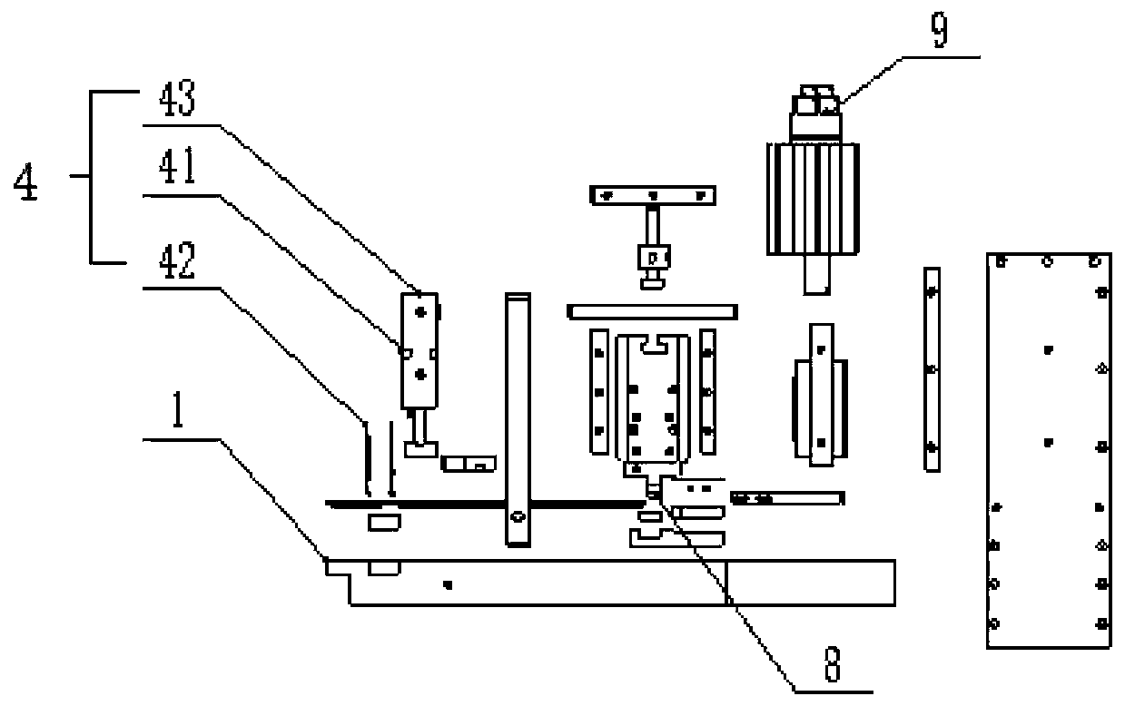
The invention relates to the technical field of electronic detonators, in particular to electronic detonator bridge wire mounting equipment. The electronic detonator bridge wire mounting equipment comprises a workbench, and a conveying mechanism for intermittently conveying a material strip is arranged on the workbench. The workbench is provided with a riveting device, a first detecting device, asecond detecting device and a rolling machine wheel from the starting end of the conveying mechanism to the tail end in sequence, the riveting device is used for riveting bridge frames on the materialstrip to be connected and formed with bridge wires, the first detecting device is used for detecting mounting of the bridge wires on electronic detonators, the second detecting device is used for detecting whether the appearances of the electronic detonators are qualified or not, and the rolling machine wheel is arranged on the workbench and used for rolling a carrying belt. The electronic detonator bridge wire mounting equipment has the advantages of replacing manual operation, achieving mechanical automatic production, and improving the production efficiency.

Description

technical field [0001] The invention relates to the technical field of electronic detonator production, more specifically, it relates to an electronic detonator bridge wire installation device. Background technique [0002] The bridge wire of the digital electronic detonator is a resistance wire welded on the two legs / electrodes. When the current passes through, the bridge wire will be heated instantly, and the heat-sensitive ignition powder wrapped around the bridge wire will be heated. When the bridge wire After the temperature of the wire reaches the ignition point of the ignition powder, the ignition powder is ignited to realize the function of the component. [0003] In addition, a bridge wire positioning structure of a digital electronic detonator is provided. The bridge wire positioning structure is constructed with positive and negative electrodes of electrodes. The positive and negative electrodes of the electrodes are respectively provided with bridges bent and arr...

Claims


Application Information

Patent Timeline
IPC IPC(8): F42C17/04F42C19/12
CPCF42C17/04F42C19/12
Inventor 吴琼覃勇波程恩轮吴楠
Owner 东莞市弘腾自动化智能科技有限公司
Learn More