Support wing aircraft

A technology for supporting wings and aircraft, applied in the direction of wings, aircraft parts, fuselage, etc., can solve the problem of not setting the wing interconnection area, and achieve the effect of reducing cost and weight, reducing relative quantity, and simplifying wing components

Active Publication Date: 2020-06-23
AIRBUS HELICOPTERS DEUT GMBH
View PDF15 Cites 0 Cited by
  • Summary
  • Abstract
  • Description
  • Claims
  • Application Information

AI Technical Summary

Problems solved by technology

However, these "multi-box wing" designs are only described in relation to aircraft having a single wing, so that the described "multi-box wing" designs do not provide for implementing box-wing or joint-wing structures in strut-wing aircraft. desired arbitrary wing interconnection area

Method used


Image

  • Support wing aircraft
  • Support wing aircraft
  • Support wing aircraft

Examples


Embodiment Construction

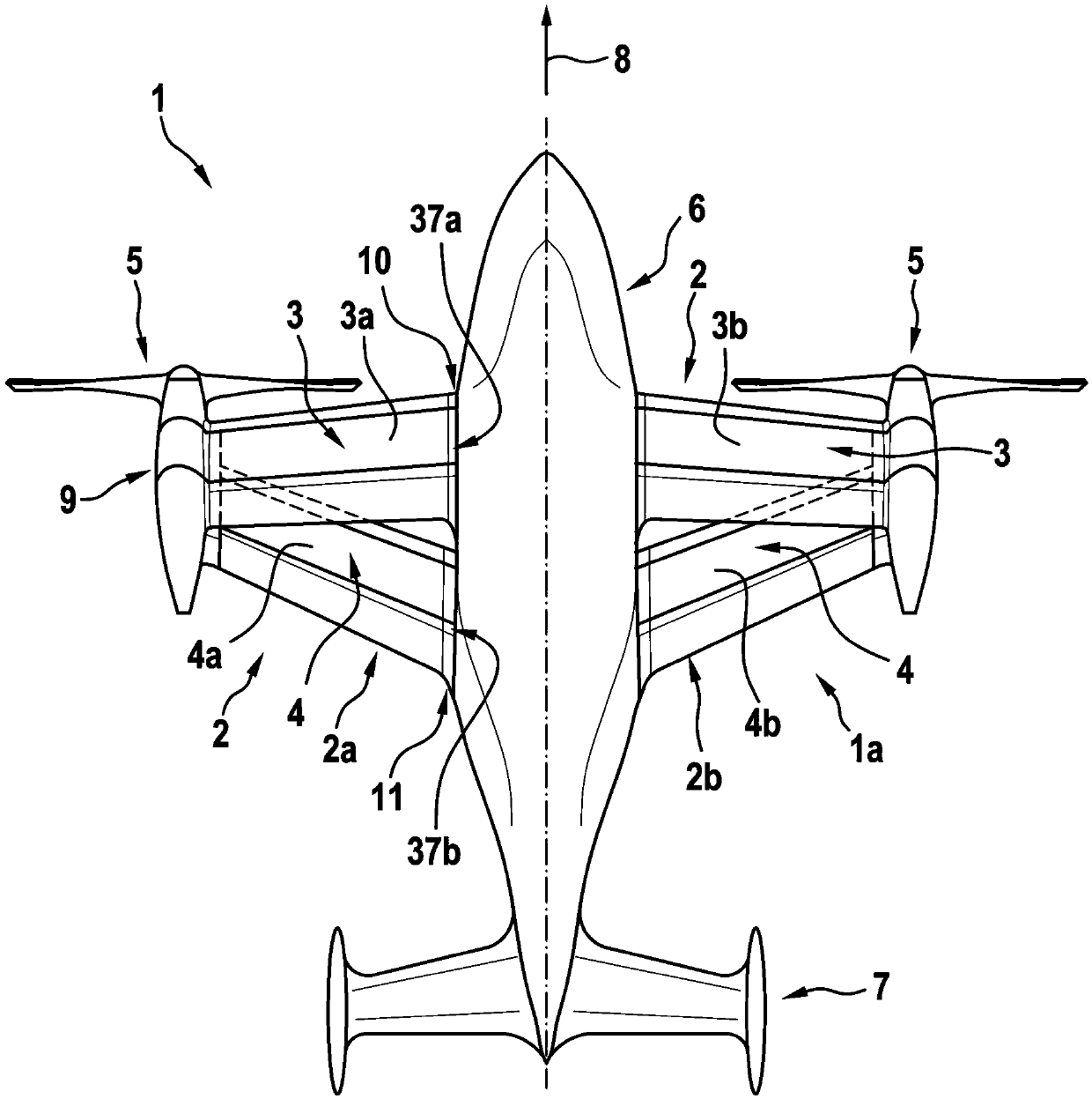
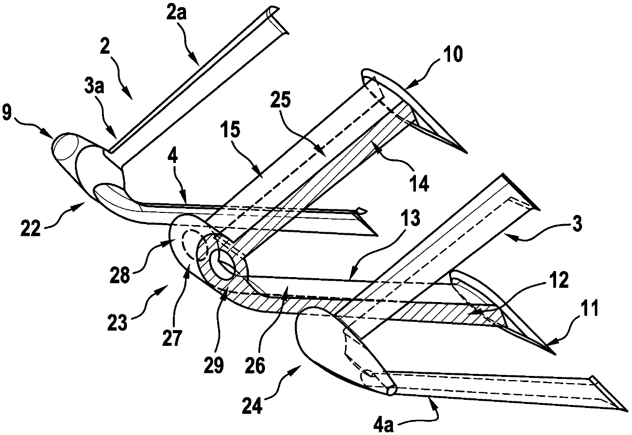
[0057] figure 1A strut-wing aircraft 1 is shown having a fixed-wing configuration 1 a and a fuselage 6 . The fixed wing configuration 1a preferably comprises two or more support wings 2 provided with an upper wing 3 and a lower wing 4 each. Schematically, the fixed-wing configuration 1a includes a first supporting wing 2a and a second supporting wing 2b, which are arranged on the side of the fuselage 6 and facing each other. The first support wing 2 a is exemplarily mounted to the starboard side of the support wing aircraft 1 , and the second support wing 2 b is exemplarily mounted to the port side of the support wing aircraft 1 .

[0058] According to one aspect, the supporting wing 1 is provided with suitable propulsion means 5 and empennage 7 . Schematically, the propulsion means 5 are represented as pull-in propellers, but they may also be represented as push-type propellers. Likewise, the propulsion means 5 may be fixedly mounted or alternatively embodied as a tilted r...


PUM


Abstract

The invention relates to a support wing aircraft (1). The aircraft comprises an aircraft body (6) and a fixed wing structure (1a); the fixed wing structure (1a) comprises at least two support wings (2a, 2b); the at least two support wings (2a, 2b) are arranged on the side face of the aircraft body (6) and are opposite to each other; each of the at least two support wings (2a, 2b) comprises at least one upper wing (3a, 3b) and at least one lower wing (4a, 4b); the at least one upper wing (3a, 3b) and the at least one lower wing (4a, 4b) are interleaved and interconnected at a predetermined transition region (9); the at least one upper wing (3a, 3b) is connected to the aircraft body (6) at an associated upper wing root (10); and the at least one lower wing (4a, 4b) is connected to the aircraft body (6) at an associated lower wing root (11).

Description

technical field [0001] The invention relates to a strut wing aircraft, which has a fuselage and a fixed wing configuration, the fixed wing configuration comprising at least two strut wings arranged on the side of the fuselage and facing each other. Background technique [0002] Aircraft with strut wings, in particular with so-called box-wing or joint-wing structures, have long been known. In general, such box wing or joint wing structures are based on relatively complex configurations of the main load-carrying members (such as wings, ribs, and spars) that require the respective upper and lower wings connected together in a sufficiently efficient manner. [0003] However, when using upper and lower wings formed on the basis of conventional wing structures, in particular based on conventional staggered strut wing structures, multiple kinks often form in the associated spars at least in the respective wingtip regions. This leads to increased structural complexity at least in ...

Claims


Application Information

Patent Timeline
Patent Type & Authority Applications(China)
IPC IPC(8): B64C1/00B64C3/00
CPCB64C1/00B64C3/00
Inventor 马丁·布拉查阿克塞尔·芬克
Owner AIRBUS HELICOPTERS DEUT GMBH
Why Eureka
Try Eureka