Electrically driven rotator cuff repair instrument

An electric drive and prosthetic technology, applied in the field of medical devices, can solve problems such as high difficulty in operation, further improvement of practicability, obstacles to popularization of devices and practical use

Pending Publication Date: 2020-06-12
苏州市永旭精密五金制品厂
View PDF0 Cites 3 Cited by
  • Summary
  • Abstract
  • Description
  • Claims
  • Application Information

AI Technical Summary

Problems solved by technology

When using a flexible thread with shape memory to pass through the area of ​​the tissue to be sutured, the existing corresponding instruments generally require the cooperation of multiple people in practical applications, and the operation is relatively difficult, and the cooperation of multiple people is also difficult. Sufficient skill and tacit understanding are required, which hinders the promotion and practical use of this kind of equipment, and the practicality needs to be further improved.

Method used


Image

  • Electrically driven rotator cuff repair instrument
  • Electrically driven rotator cuff repair instrument

Examples


Embodiment Construction

[0012] The present invention will be further described below in conjunction with the accompanying drawings and specific embodiments.

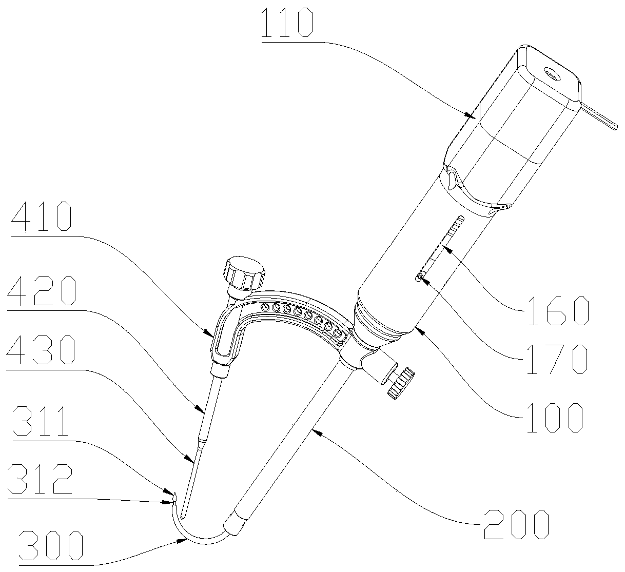
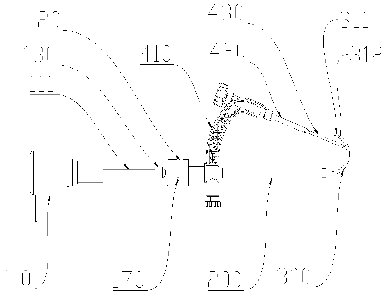
[0013] like figure 1 and figure 2 An electrically driven rotator cuff repair instrument is shown, including a prosthesis main body 100, a sleeve 200 and a bone pin 300, the sleeve 200 is arranged at the lower end of the prosthesis main body 100, and the bone pin 300 is set on the sleeve 200, the prosthesis main body 100 is provided with a driving structure that drives the bone needle 300 to slide in the cavity of the sleeve 200, and the puncture part protruding from the sleeve 200 at the lower end of the bone needle 300 is in a predetermined curved shape. The end of the bone needle 300 is provided with a tip 311 and a threaded port 312 for driving sutures. The driving structure includes a motor 110 and a transmission cylinder 120. The motor 110 is fixed on the upper end of the prosthesis main body 100 and connected to an external power supply...


PUM


Abstract

The invention relates to the field of medical instruments. The invention discloses an electrically driven rotator cuff repair instrument. The device comprises a restorer main body, a sleeve and bone needles, the sleeve is arranged at the lower end of the restorer main body; the bone needle is arranged in the sleeve; a driving structure for driving the spicule to slide in the cavity of the sleeve is arranged on the restorer main body; the puncture part, protruding out of the sleeve, of the lower end of the spicule is in a preset bent shape; the tail end of the bone needle is provided with a tipend and a thread port for driving a suture; the driving structure comprises a motor and a transmission column body; the motor is fixed at the upper end of the restorer main body and connected with anexternal power supply, a cylindrical cavity is formed in the restorer main body, the transmission column body is located in the cylindrical cavity, the motor is connected with the upper end of the transmission column body and can drive the transmission column body to coaxially move in the cylindrical cavity, and the lower end of the transmission column body is connected with the upper end of thebone needle. The bone needle can be operated by a single person when used for puncturing and withdrawing, and is simple to operate and high in practicability.

Description

technical field [0001] The invention relates to a medical device, in particular to an electrically driven rotator cuff repairing device. Background technique [0002] With the development and progress of technology, various medical devices have been developed for pathological symptoms. The rotator cuff repairer is a tool to help surgeons pass sutures through bones, especially for sutures that need to be placed along non-linear lines. The many operations that the "path" traverses. When using a flexible thread with shape memory to pass through the area of ​​the tissue to be sutured, the existing corresponding instruments generally require the cooperation of multiple people in practical applications, and the operation is relatively difficult, and the cooperation of multiple people is also difficult. Sufficient skill and tacit understanding are required, which hinders the promotion and practical use of this kind of equipment, and the practicality needs to be further improved. ...

Claims


Application Information

Patent Timeline
IPC IPC(8): A61B17/04
CPCA61B17/0482
Inventor 袁朝仁
Owner 苏州市永旭精密五金制品厂
Why Eureka
Try Eureka