A vehicle speed control method and system

A technology of vehicle driving speed and driving speed, which is applied in the direction of electric braking system, control device, vehicle components, etc., which can solve the problems of high hardware cost, sudden change of vehicle deceleration, and inability to realize linear adjustment of electric braking intensity, etc., and achieve improvement Energy consumption levels, balancing contradictory effects

Active Publication Date: 2021-11-23
GAC AION NEW ENERGY AUTOMOBILE CO LTD
View PDF5 Cites 0 Cited by
  • Summary
  • Abstract
  • Description
  • Claims
  • Application Information

AI Technical Summary

Problems solved by technology

The greater the energy recovery rate, the stronger the electric braking intensity. When the electric braking intensity cannot match the driver's expected vehicle braking intensity, there will be an irreconcilable contradiction between the energy recovery rate and driving comfort.
[0003] There are currently three high-intensity electric braking technical solutions, (1) The braking system is upgraded to a serial braking system. This type of system can be freely switched between electric braking and hydraulic braking. When the driver brakes When the demand is less than the set threshold, full electric braking can be realized, and the intensity of electric braking can be changed according to the opening of the brake pedal. The hardware cost of this solution is high. After the hardware specification is set, the maximum set threshold of electric braking cannot Continue to increase through the software; (2) Set different levels of electric braking strength, the driver can adjust the electric braking strength in real time according to needs, the electric braking strength cannot be adjusted linearly in this scheme, when the electric braking strength level changes There is a sudden change in the deceleration of the vehicle; (3) Taking the change of vehicle speed as the control target, when the vehicle speed exceeds the speed set by the accelerator pedal opening, it will actively trigger the electric brake to reduce the vehicle speed, and the electric brake can be controlled by the change of the accelerator pedal opening. Braking intensity, this scheme does not consider the driver's deceleration intention, even if the driver has no deceleration intention, when the vehicle speed increases due to downhill or other reasons, the on-board computer will actively trigger the electric brake to reduce the vehicle speed
[0004] It can be seen that in the prior art, the driver's deceleration intention is not fully considered, and the vehicle speed change is the control target.

Method used


Image

  • A vehicle speed control method and system
  • A vehicle speed control method and system

Examples


Embodiment 1

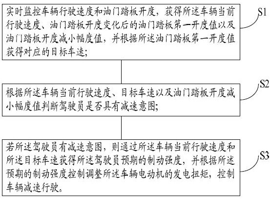
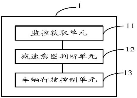
[0058] Based on the first embodiment of the present invention, the second embodiment of the present invention provides a vehicle speed control system, such as figure 2 As shown, the system 1 includes:

[0059] The monitoring acquisition unit 11 is used to monitor the vehicle speed and the opening degree of the accelerator pedal in real time, obtain the first opening degree value of the accelerator pedal after the current driving speed of the vehicle, the opening degree of the accelerator pedal and the value of the reduction range of the opening degree of the accelerator pedal, and according to The first opening value of the accelerator pedal obtains the corresponding target vehicle speed;

[0060] Deceleration intention judging unit 12, for judging whether the driver has a deceleration intention according to the current driving speed of the vehicle, the target vehicle speed, and the value of the reduction magnitude of the accelerator pedal opening;

[0061] The vehicle trave...


PUM


Abstract

The present invention provides a vehicle speed control method and system. The method includes: monitoring the vehicle speed and the opening of the accelerator pedal in real time, and obtaining the current speed of the vehicle, the first opening value of the accelerator pedal after the change of the opening of the accelerator pedal, and the value of the first opening of the accelerator pedal. Decrease the pedal opening value, and obtain the corresponding target vehicle speed according to the first opening value of the accelerator pedal; judge whether the driver has decelerated according to the current driving speed of the vehicle, the target vehicle speed, and the decreasing amplitude value of the accelerator pedal opening Intent; if the driver has the intention to decelerate, then obtain the driver's expected braking intensity through the vehicle's current driving speed and the target vehicle speed, and control and adjust the vehicle motor according to the expected braking intensity The power generation torque of the control vehicle decelerates. The invention balances the contradiction between the electric braking intensity and the driver's comfort, and improves the energy consumption level of the vehicle.

Description

technical field [0001] The present invention relates to the technical field of vehicle control, in particular to a vehicle speed control method and system. Background technique [0002] As energy consumption and emission standards become more and more stringent, various configurations of new energy vehicles have become the research and development focus of various automobile manufacturers, and the energy recovery rate directly affects energy consumption and emission levels. The greater the energy recovery rate, the stronger the electric braking intensity. When the electric braking intensity cannot match the driver's expected vehicle braking intensity, there will be an irreconcilable contradiction between the energy recovery rate and driving comfort. [0003] There are currently three high-intensity electric braking technical solutions, (1) The braking system is upgraded to a serial braking system. This type of system can be freely switched between electric braking and hydrau...

Claims


Application Information

Patent Timeline
Patent Type & Authority Patents(China)
IPC IPC(8): B60L7/00
CPCB60L7/00B60L2240/12B60L2240/423B60L2250/26
Inventor 黎润东谭长平高天一刘方苏建云
Owner GAC AION NEW ENERGY AUTOMOBILE CO LTD
Why Eureka
Try Eureka