Electronic pneumatic separating and closing executing mechanism

An electro-pneumatic and actuator technology, applied to clutches, mechanical equipment, etc., can solve problems such as long response time, low transmission efficiency, and complex systems, and achieve the effects of reducing clutch plate wear, eliminating bumps and other vibrations

Pending Publication Date: 2020-05-12
RUILI GROUP RUIAN AUTO PARTS CO LTD
View PDF0 Cites 1 Cited by
  • Summary
  • Abstract
  • Description
  • Claims
  • Application Information

AI Technical Summary

Problems solved by technology

At present, there are mainly two types of actuators for automatic clutches: hydraulic and electric, but the hydraulically driven automatic clutch system requires a hydraulic system such as a motor pump and an oil tank, and the system is complicated.
The motor-driven clutch actuator uses a DC motor as the power source. Although the structure is simple, the transmission efficiency is low, resulting in a long response time.

Method used


Image

  • Electronic pneumatic separating and closing executing mechanism
  • Electronic pneumatic separating and closing executing mechanism
  • Electronic pneumatic separating and closing executing mechanism

Examples


Embodiment Construction

[0025] The content of the present invention will be clearly and completely described below in conjunction with the accompanying drawings. Apparently, the described embodiments are part of the embodiments of the present invention, not all of them. The embodiments in the present invention and other embodiments obtained by persons of ordinary skill in the art without creative efforts all belong to the protection scope of the present invention.

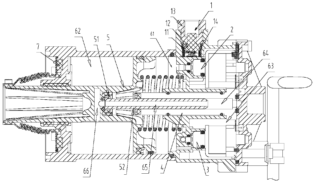
[0026] figure 1 It is a structural schematic diagram of the electropneumatic clutch actuator of the present invention. Such as figure 1 As shown, this state is the initial diagram after the electropneumatic clutch actuator is loaded. When a group of separation solenoid valves 2 are not powered, the solenoid valves seal the air pressure input from the air inlet 1 and prevent the air pressure from entering the first air cavity 61 . A valve spring 11 and a one-way valve 12 can be installed on the air inlet 1 to prevent the reverse output ...


PUM


Abstract

The invention discloses an electronic pneumatic separating and closing executing mechanism. The electronic pneumatic separating and closing executing mechanism is provided with a gas inlet (1), a separating solenoid valve (2), a closing solenoid valve (3), a travel sensor assembly (4), a pneumatic piston (5), a first gas cavity (61) and a second gas cavity (62). When the separating solenoid valve(2) is electrified and the closing solenoid valve (3) is not electrified, high-pressure gas enters the first gas cavity (61) from the interior of the separating solenoid valve (2) via the gas inlet (1), so that the pneumatic piston (5) is pushed to move towards one side, and a clutch is separated; and when the separating solenoid valve (2) is not electrified and the closing solenoid valve (3) is electrified, the high-pressure gas enters the second gas cavity (62) from the first gas cavity (61) via the interior of the closing solenoid valve (3), so that the pneumatic piston (5) is pushed to move towards the other side, and the clutch is closed. The travel sensor assembly (4) records the confirmed clutch position and provides the confirmed clutch position to a transmission box control unit,and thus electronic pneumatic separating and closing are achieved.

Description

technical field [0001] The invention relates to an electronic pneumatic clutch actuator, in particular, it belongs to the electronic pneumatic clutch actuator in the field of automobile braking. Background technique [0002] With the development of the automobile industry, the clutch system gradually tends to be automated. The actuator of the automatic clutch is the core component. At present, there are mainly two types of actuators for automatic clutches: hydraulic and electric. However, the hydraulically driven automatic clutch system requires a hydraulic system such as a motor pump and an oil tank, and the system is complicated. The motor-driven clutch actuator uses a DC motor as a power source. Although the structure is simple, the transmission efficiency is low, resulting in a long response time. [0003] However, the present invention aims at the defects and deficiencies of the prior art, and provides a clutch actuator with reasonable design, simple structure and con...

Claims


Application Information

Patent Timeline
Patent Type & Authority Applications(China)
IPC IPC(8): F16D48/06
CPCF16D48/066F16D2500/1045F16D2500/5023F16D2500/70605
Inventor 李传武王鲜艳陈波李斌斌杨业裕王新泽许振好
Owner RUILI GROUP RUIAN AUTO PARTS CO LTD
Why Eureka
Try Eureka